
X10 project #3 |
|
| Back to main X10 projects page | |
| - | |
| I have a machine shop area in my shop where I cut, sand and drill glass epoxy circuit board material. I needed the dust collection shop vacuum to turn on every time I use one of the 3 machines that creates dust. Turning it on and off manually was a pain and I would just skip it half the time and try not to breath the dust. In the project below, I take a 6 plug powerstrip and install a current sensing circuit inside. The 3 dust making machines get plugged into the powerstrip. Any time I turn on any one of the 3 machines an X10 Powerflash unit will turn on a X10 - SR227 wall receptacle module. My dust collection shop vacuum is plugged into the X10 - SR227 wall receptacle and will then turn on automatically. |
|
| - | |
| Here's a diagram of how this project works The CR3110 senses current flowing in the Black AC hot wire that leads to a AC Load. A small AC voltage appears on the two CR3110 secondary wires. A bridge rectifier turns the AC voltage into pulsating DC voltage. The 100uf cap smoothes out the pulsating DC into smooth DC. The 10K resistor is a load resistor. The X10 Powerflash senses voltage on it's + and - terminals and then sends an X10 code when it is triggered. The X10 - SR227 receives the X10 code from the Powerflash and turns on the top outlet. Anything plugged into the top outlet of the SR227 with turn on. |
|
 |
|
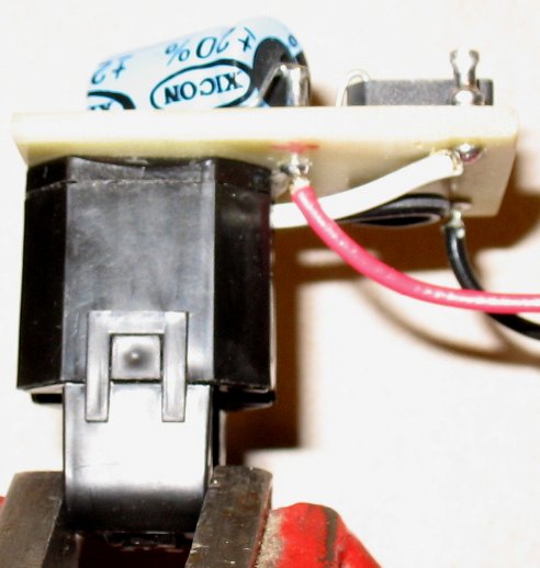
| Notes: A load is something that uses power, like a toaster, drill press, Jig Saw, etc. The Powerflash is plugged into a non current sensing AC receptacle in the powerstrip or into any wall receptacle. You can use any X10 device as the receiver and do whatever it is you need done. The voltage rating of the Bridge and 100UF Capacitor probably need to be 50 volts at the very least. I used parts that I already had on hand in my shop, the parts are not critical. The CR3110-3000 is a current sensor that is made and sold by CR Magnetics Inc. 3500 Scarlet Oak Blvd. St Louis, MO, 63122 http://www.crmagnetics.com/newprod/ProductView.asp?ProdName=CR3110 |
|
| - | |
 |
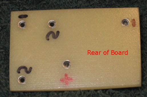 |
| Here's a front and back shot of the circuit board that I will install inside my power strip. It had to be small to be able to fit inside the powerstrip. |
|
| - | |
| Click on the image below for a larger image. | |
 |
|
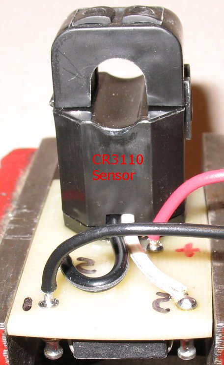
| I epoxied the CR3110 current sensor to the back of the circuit board to keep it from moving around. | |
| - | |
| Click on the image below for a larger image. | |
 |
|
| The complete board assembly with the CR3110 epoxied to the back. | |
| Click on the image below for a larger image. |
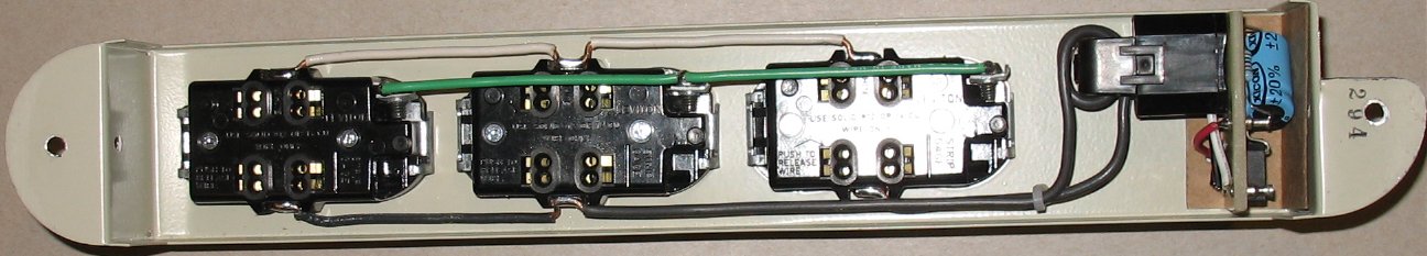 |
| Here's the Cr3110 circuit board assembly mounted inside the power strip. The four AC receptacles on the left are the current sensing receptacles, they must flow current through the CR3110. The two AC receptacle on the right do not flow through the CR3110. Note: Each black AC receptacle in the pictures actually has two AC receptacles. |
| - |
| Click on the image below for a larger image. |
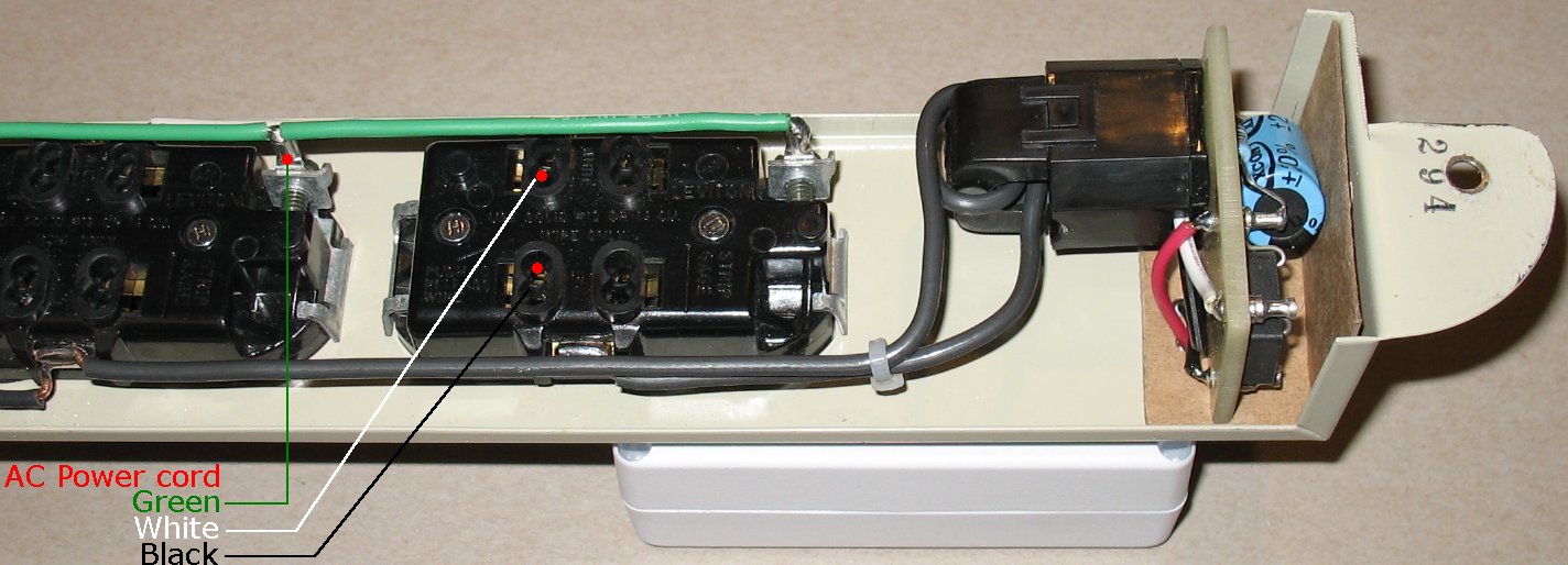 |
| Note the two turns of 12 gauge solid core wire through the hole in the CR3110. Click on the photo above to see how to connect the Powerstrip AC power cord. |
| - |
| Click on the image below for a larger image. |
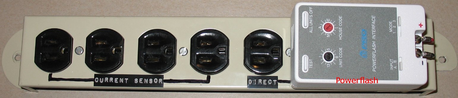 |
| The front side of the power strip. There are 6 total AC receptacles. There is four current sensing AC receptacles on the left and two non sensing AC receptacles on the right. The Powerflash is plugged into the far right AC receptacle. |
| - |
| Click on the image below for a larger image. |
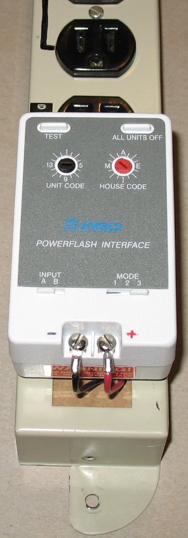 - - |
| End view of the X10 Powerflash unit. The Black Negative and Red Positive wires from the circuit board are connected to the Powerflash - and + terminals. The Powerflash is set to Input A (voltage sensing input) and Mode 3 (turn on all X10 units set to the same code as the Powerflash) I set the Powerflash house code to the same code as the SR227 appliance module that I will be controlling. |
| - |
| Click on the image below for a larger image. |
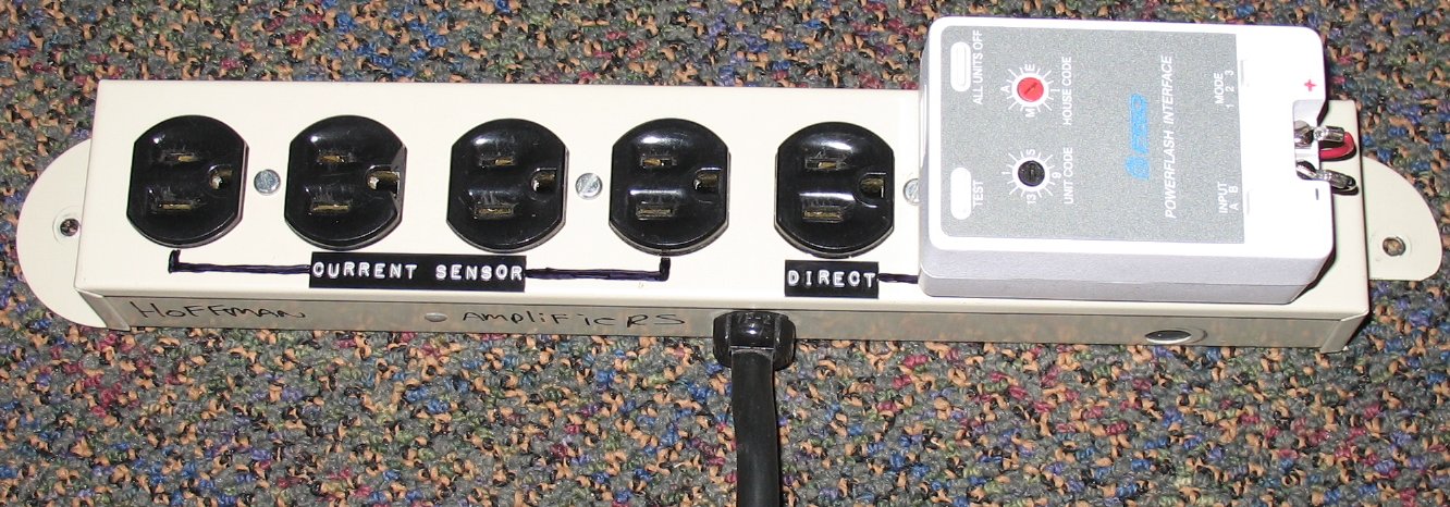 |
| Here's the power strip fully assembled with the AC power cord. |
Enter My Tube Amp Parts Store Here
Mobile users Enter My Tube Amp Parts Store Here
The Tube amp Library of information
Click the link above for Tube amp info, Schematics, Board building information, Projects, Mods, Transformer diagrams, Photo's, Sound clips.
There are hundreds of pages of Tube amp information on my library page.
Please visit my Tube Amplifier Forum
Here's the place you can go to ask tube amplifier questions.
You will find a large community of friendly amp builders at the link above.
Check the huge library of Schematics here
Design your own custom Turret Board or Eyelet board
DIY Layout Creator file analyzer program
DIY Layout Creator file library
Sound clips and tunes of all types
How to email me
|
MEMBER OF PROJECT HONEY POT Spam Harvester Protection Network provided by Unspam |