Hi Guys,
I undertook the task of helping a friend out with building him a single channel AB763 Deluxe Reverb using a Hoffman Board. The donor amp was an old busted up ELK, but the transformers seemed good and had the same values/ratings as a Deluxe Reverb.
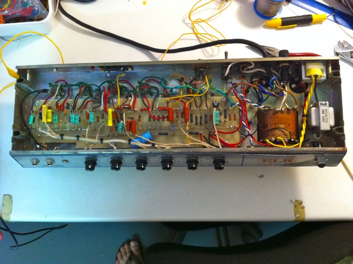
The only caveat is that the PT didn't have a BIAS tap, so on recommendation from a couple of the guys over in
this thread I bought a small 100mA 12-0-12/240VAC trano and hooked up the 24V to the 6VAC heaters for a +- 55VAC BIAS, that worked like a charm. I also added in a choke as the donor amp didn't have one.
As you will see the chassis is alot smaller than the Fender ones and it's a tight squeeze, also had to add another 9 Pin tube socket into the mix.
Now let me say I'm fairly proficient with electronics building DIY kit for several years, though largely solidstate and am always learning about valves/tubes circuits, done a bunch of cap jobs etc, but this is only my 2nd scratch build after a successful 5F1 build.
Where I'm at is having triple checked my connections and the PT voltages I inserted the tube rectifier and it is working, I'm getting 420VDC on the first filter cap stage as well as -27VDC on the BIAS, where it should be +- -35VDC, but I've not trimmed it yet. I've also not wired up the reverb trano as currently I don't have a reverb tank, but the rest of the connections have been soldered as per normal.
I know that unloaded voltages are higher than the documented ones on the original Fender documents, but I'm puzzled as with no load, i.e no tubes fitted, I should be getting +-180VDC on PIN 1 of the first preamp stage, currently it is 420VDC, the same voltage as my HV rail, infact currently ALL my HV caps are sitting at the 420VDC I'm getting after it has been rectified.
I've checked and rechecked my ground plains, I have continuity between all the points, power section on one end, audio on the other, though all bolted to the chassis, at the same ground potential.
Any thoughts? Maybe I missed something?
Thanks in advance.

 Topic: Troubleling voltages on a Hoffman AB763 build (Read 7305 times)