There has been recent discussion of low powered push pull amplifiers, and tubenit has collated and archived useful circuits and design ideas.
http://www.el34world.com/Forum/index.php?topic=12526.msg117936#newThis design is another such amplifier, but using a dual tetrode output valve. I have, in the past, attempted to use small signal dual triodes, such as the 12AU7 or 6SN7 as push-pull output valves, but always found the results disappointing. The valve chosen for this project is the Soviet-era dual tetrode GU-17, which is electrically equivalent to the QQE 03/12 and the 6360.
http://tubedata.milbert.com/sheets/018/g/GU17.pdfhttp://tubezone.net/pdf/6360.pdfThe GU-17's are available at low cost from several of the online Russian and Ukrainian valve vendors. One useful feature of the GU-17 and its equivalents is a 12.6 volt centre-tapped heater, making it very easy to use a solo GU-17 with this amplifier's 12 volt heater supply.
The original idea when these valves were purchased was a self-split output stage, so a complete push-pull amplifier could be built using just two valves - a twin triode preamp valve and the GU-17. I decided to first build a more conventional amplifier to use as a benchmark for a future self-split design, and this amp is the result.
Using a dual output valve with a separate phase inverter in the circuit described here does not actually reduce the required number of valves - a pair of 6BM8's, for example, would produce the same result, but it's more fun to do something different.

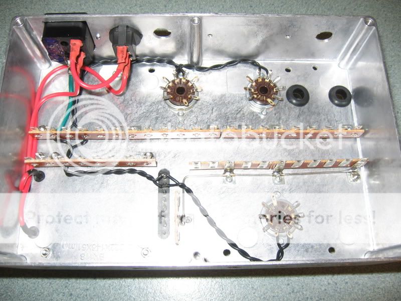
Enough talk, it's on with the construction. The chassis for this amplifier is the same one I have used for many low powered amplifiers - a diecast aluminium box similar in size to a Hammond 1550G. After drilling, filing and punching, the chassis was beaten into submission, and the valve sockets and protective grommets fitted.

Next were the tagstrips and the power transformer. The 50VA toroidal power transformer is a type used for several previous amplifiers. It has four 12VAC 1A secondaries - one is used to power the heaters, while the other three are connected in series to supply the B+ voltage, using a voltage multiplier.

The heater wiring was run hard down on the chassis from the transformer to the valve sockets, but also to tags, where hum balancing resistors would be fitted. The IEC power inlet socket and the power switch were installed on the back panel, 240VAC wiring to the power transformer was installed and exposed terminals sheathed with heatshrink tubing. An earth ( or ground ) lead was run from the IEC connector to a firmly attached lug on the nearest tagstrip.
To be continued . . .

 Topic: Push Pull Output From A Single Bottle (Read 23901 times)