My 6V6 P-P build is one I tweaked so many times . When one starts a built you start with the tranny's and the tube sockets and heater wires . Well I do . Then you start with a new eyelet board and insert all the resister and cap leads with the wire leads and bend over the leads and add in the under board leads and with room to work make real nice solder joints . I even might use a filter cap lead and to get it to the best ground point to keep the reservoir cap at a different ground point than the input section I line up the filter caps and run the neg side of a new filter cap under the eyelet board to a spare eyelet then to ground so I don't have to force 4 leads into one eyelet. But then the tweaking comes along to get the sound you want and then you need to cut one of the nice jumpers you made and un-solder and remove all the old solder and some solder joints come out fine and others that are difficult to reach are no longer the nice eyelet with just enough solder where the eyelet was once filled with just a slight dip in the center and now is a taller but shiny little hill.
I don't have a solder station and even got a smaller tip for my 40 watt weller marksman which came with a huge 1/4" chisel tip so I got the 1/8" screw driver tip thinking it would work great since it has a small dia barrel or heater and it's long enough to reach in tight spots without the fear of melting something near but the damn weller was to hot . I went back to the old unger which had this rather large ceramic heating element and it's marked on the heater 37 1/2 watt 110 VAC and 44 watt at 120VAC yet even with the same size 1/8" screwdriver tip it works perfect . The drawback is the large dia ceramic heater had to be 3/4" dia and is half the length of the entire shank .
Both the weller and ungar are close to the same wattage and tip size yet one works better , doesn't make sense to me.
I use a spool or 18AGW with an alligator clip as a heat sink to keep the heat off the filter caps when making changes and even small heat sinks for resisters and small caps just to play it safe . I just feel like making a new eyelet board much smaller so I have more room and going back to the old cloth solid core wire and get new F&T filter caps and start over . It all works fine now . I thing the only things I have not soldered more than once are the heater leads and PT and OT leads . I stuffed a lot of amp into a small 77 fender music master bass amp chassis and used this huge weber 5E3 fiber eyelet board .
This is what it looked like before I added one more filter cap .
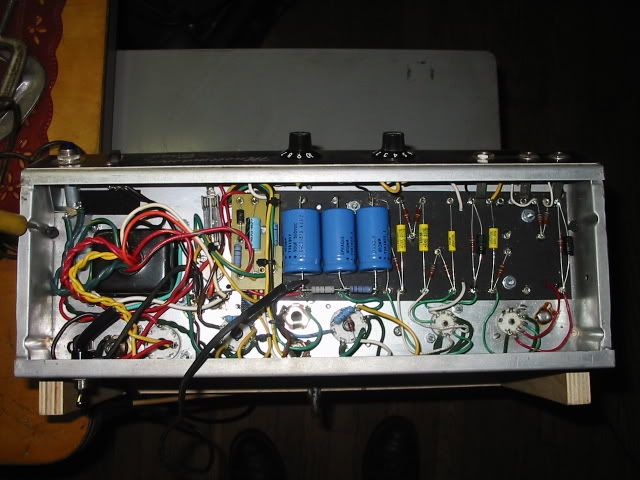
Now I moved the bias board off the fiber board and placed it between the end of the fiber board and the PT and moved the B+ fuse over to the far left side of the chassis on the inside of the right side near the top of the side centered between the strap bolt holes and mounted the bias board closer to the front of the amp and have it on a tall nylon standoff to keep chassis heat from it. Then moved the reservoir cap over to the eyelets that used to be used for a cathode bias resister and cap , then placed a new 16uf sprague filter cap where the reservoir cap was and added on more dropper . It really looks packed full now. I even shortened the leads between the output sockets and on the PI to V2 . If I made a new eyelet board of the 1/8" hoffman stock I could make the board 1/3 the size and then fit the much smaller F&T filter caps and be able to at least get at the filter cap ground ends and make a new bias board just a bit smaller. Course this will have to wait some time until I find the funds . You can't even see the three resisters for the PI since the sprague caps are so large. Something tells me the weber eyelet board was not designed to use sprague filter caps.
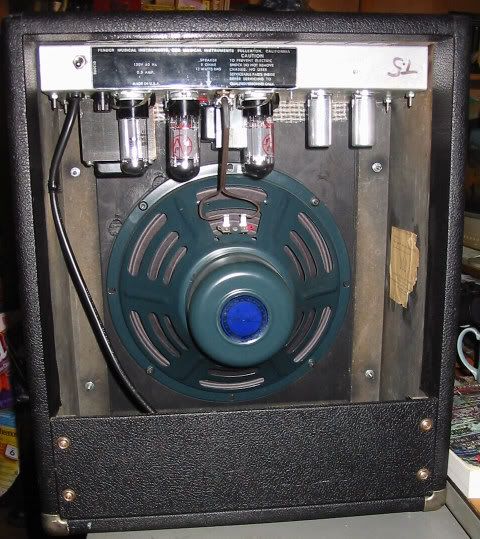
This is the back view showing the size of the PT and OT .
If I had room I would use a cap can or the cover and put the caps under the chassis like the BFDR .

 Topic: Have you ever tweaked a built so many times you feel like re-doing it? (Read 4965 times)