Welcome To the Hoffman Amplifiers Forum

September 07, 2025, 02:33:33 am
guest image
Welcome, Guest. Please login or register.
-User Name
-Password


Hoffman Amps Forum image Author Topic: unusual phase invertor?  (Read 22556 times)

0 Members and 1 Guest are viewing this topic.

Offline DummyLoad

  • SMG
  • Level 5
  • *****
  • Posts: 5791
Hoffman Amps Forum image
Re: unusual phase invertor?
« Reply #50 on: August 10, 2013, 05:22:36 am »
OK, sulzer PI does work with the 6SJ7; kinda_sort_of... the phases are 180o out as expected, however, the output level symmetry is WAaaaY off - about 1:3.2 - the screen output is MUCH hotter then the plate output.

built with the following components & values:
6SJ7 - NOS DuMont.
Ra = 220K
Rsg = 100K
Rgleak = 1M
Rk = 560R
Rtail = 22K
Cbyp = 47uF @ 63V
Cin .1uF @ 200V
Cc .022uF 400V

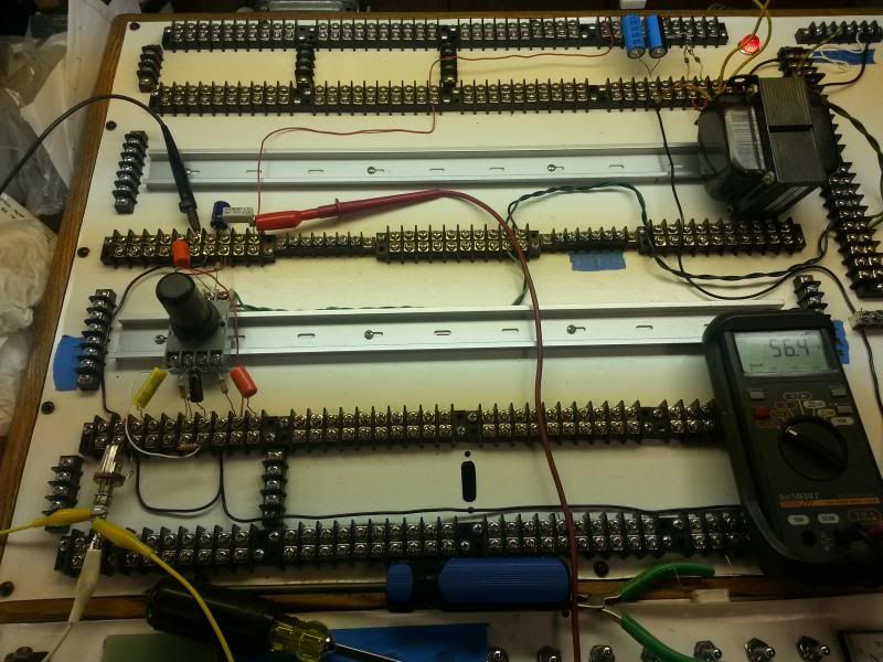
all measurements referenced to ground at idle and no input signal:
Line 110V
B+ ~ 335V
vk ~ 52V
va ~ 315V
vsg ~ 115V
vr-k ~ 1.31V

Vin is 1Vpk to CH1 of the scope (lower trace) CH1 is the triggering source for CH2.
Vout screen ~8Vpk
Vout anode ~2.5Vpk

anode output - using 10X probe 1V/div:


screen grid output - using 10X probe 2V/div:


as built:

 
perhaps what we are needing is a higher gm tube after all. i suspect the higher slope valve probably has a larger space charge for the plate to draw from so the outputs would have greater symmetry than what i'm observing with the 6SJ7. sulzer mentions in his article that the symmetry is tuned by adjustments to the anode resistor value and not the screen resistor value since altering the screen resistor changes the symmetry of both outputs. oh well...the road to hell...
 
as already noted, if this thing were the bee's knees, it'd be omnipresent, however, my thoughts are that it's someones experiment that has some merit in that it likely does work if built as published. my guess is it'd be a one_trick_pony at best. just for curiosities sake, i'll give it another round in the ring, but this time with the higher gm 6AU6, since i don't have any inventory of the 6AC7 part.

respectfully,

--pete

Offline sluckey

  • Level 5
  • *******
  • Posts: 5075
    • Sluckey Amps
Hoffman Amps Forum image
Re: unusual phase invertor?
« Reply #51 on: August 10, 2013, 07:56:33 am »
Your anode signal is in phase with the control grid signal??? Man, that's messing me up. You don't have an invert button pushed somewhere do you?    :w2:
A schematic, layout, and hi-rez pics are very useful for troubleshooting your amp. Don't wait to be asked. JUST DO IT!

Offline Willabe

  • Global Moderator
  • Level 5
  • ******
  • Posts: 10524
Hoffman Amps Forum image
Re: unusual phase invertor?
« Reply #52 on: August 10, 2013, 08:06:44 am »
IN THE NORMAL METHOD of operation a single-stage amplifier will produce a phase reversal between the input and output voltages. Pentodes when operated in this way have a screen-grid voltage supplied by a source with a very low internal impedance. It is known that the screen-grid supply impedance will produce a degenerative effect, decreasing the gain of the amplifier.'  Further study has indicated that this effect might be increased to the point where the amplifier gain would he zero, and that a still greater increase in screen-supply impedance would cause the amplifier gain to increase from zero, but with opposite phase.

so what mr. sulzer is saying is: if you move the supressor grid and connect it to ground, add enough impedance to the screen supply, you've manipulated the behavior of the space charge between the elements so that the plate phase will follow the phase of the control-grid and the screen grid will then act similar to a conventional amplifier and invert phase. so now one has a single tube phase-inverter with gain...OK, so what's so wrong with a CC stage coupled to a concertina? it's a single tube PI with gain... in fact, more gain than the pentode PI mr. sulzer presents.


                 Brad      :dontknow:

Offline sluckey

  • Level 5
  • *******
  • Posts: 5075
    • Sluckey Amps
Hoffman Amps Forum image
Re: unusual phase invertor?
« Reply #53 on: August 10, 2013, 08:31:22 am »
Thanks Brad. Seeing it for the first time is still unsettling.   :icon_biggrin:
A schematic, layout, and hi-rez pics are very useful for troubleshooting your amp. Don't wait to be asked. JUST DO IT!

Offline Willabe

  • Global Moderator
  • Level 5
  • ******
  • Posts: 10524
Hoffman Amps Forum image
Re: unusual phase invertor?
« Reply #54 on: August 10, 2013, 08:43:53 am »
Yeah, it's backwards alright. I think your right if it was a good PI it would have been used years ago in production.

More than 1 way to skin a cat but some are much easer than others. I think it's a throw away, like you said round file can.

But the guys are having fun, so......


                 Brad     :laugh:
« Last Edit: August 10, 2013, 08:48:25 am by Willabe »

Offline sluckey

  • Level 5
  • *******
  • Posts: 5075
    • Sluckey Amps
Hoffman Amps Forum image
Re: unusual phase invertor?
« Reply #55 on: August 10, 2013, 09:11:44 am »
Quote
But the guys are having fun, so......
Me too!
A schematic, layout, and hi-rez pics are very useful for troubleshooting your amp. Don't wait to be asked. JUST DO IT!

Offline printer2

  • Level 2
  • **
  • Posts: 235
Hoffman Amps Forum image
Re: unusual phase invertor?
« Reply #56 on: August 10, 2013, 10:18:14 am »
OK, sulzer PI does work with the 6SJ7; kinda_sort_of... the phases are 180o out as expected, however, the output level symmetry is WAaaaY off - about 1:3.2 - the screen output is MUCH hotter then the plate output.


--pete

Cool. I also like your board setup.

Offline DummyLoad

  • SMG
  • Level 5
  • *****
  • Posts: 5791
Hoffman Amps Forum image
Re: unusual phase invertor?
« Reply #57 on: August 10, 2013, 12:17:38 pm »
OK, sulzer PI does work with the 6SJ7; kinda_sort_of... the phases are 180o out as expected, however, the output level symmetry is WAaaaY off - about 1:3.2 - the screen output is MUCH hotter then the plate output.


--pete

Cool. I also like your board setup.

thank you....  :-)

--pete

Offline PRR

  • Level 5
  • *******
  • Posts: 17082
  • Maine USA
Hoffman Amps Forum image
Re: unusual phase invertor?
« Reply #58 on: August 10, 2013, 09:32:25 pm »
> Your anode signal is in phase with the control grid signal???

That's what the 1948 article claimed. With a way-negative G3, and substantial resistance to G2, *part* of the plate curve runs backward. See image from 1948 article, attached. Red-arrow is the range over which the plate "works backward".

> output level symmetry is WAaaaY off - about 1:3.2 - the screen output is MUCH hotter then the plate output.

Article says to trim the plate resistor. Trimming Rg2 upsets the backward action and you'll get messed-up. Plate voltage should have nearly no effect on current division, so a larger plate resistor should directly give larger plate output.

Though also, because plate curve is so curved, a lesser G1 bias (higher cathode current) looks-like it will shift the action into a steeper plate slope. Repeating the point that this seems to be mighty sensitve to bias.
« Last Edit: August 10, 2013, 09:35:28 pm by PRR »

Offline DummyLoad

  • SMG
  • Level 5
  • *****
  • Posts: 5791
Hoffman Amps Forum image
Re: unusual phase invertor?
« Reply #59 on: August 10, 2013, 10:19:16 pm »
Article says to trim the plate resistor. Trimming Rg2 upsets the backward action and you'll get messed-up.

i deduced that from the article as well...please read on...  :-)  

as a follow up since i've not had time to post today; been replacing brakes pads on truck and eye-ta-li-en moter-sikcle.

early this morning i tried up to 470K and as low as 100K for Ra . very little change. i did not try to shift cathode bias up or down and left Rsg unchanged at 100K.

100K was somewhat less - about 1.5Vpk, 330K was slightly more, 470K was about 2.75Vpk. threw in the towel with this tube.

respectfully,

--pete

BTW; RicharD told me to tell you hello.

hello!   :icon_biggrin:
« Last Edit: August 11, 2013, 12:59:14 am by DummyLoad »

Offline DummyLoad

  • SMG
  • Level 5
  • *****
  • Posts: 5791
Hoffman Amps Forum image
Re: unusual phase invertor?
« Reply #60 on: August 11, 2013, 01:40:12 am »
ok, so 6SJ7 can be made to work... not one to throw it all in so easily, i decided to give our lovable 6SJ7 another shot at the "will work as weirdest PI" title. he shone like a diamond; here's what you have to do:

Ra = Rg2 = 220K
Rk = 330R
Rtail = 22K
Rgridleak = 1M
Cc = .022uF
Cin = .1uF

all measurements ref. to ground @ 110V line, except vr-k measurement:

B+ = 345V
va = 275V
vg2 = 77V
vk = 34.1V
vr-k = .51V

so then AV ~ 15. not too shabby i guess. with this new information, it would seem that with lower gm tubes the source impedance of the screen supply needs to be raised. does that make sense?

i have not over-driven it or seen what the outputs will look like loaded [there are no load resistors attached to the output coupling caps; Rload is basically infinity]. that's next.

10x probe in CH1 (1Vpk in); 10X probe in CH2; CH2 trigger source is CH1.

this pic - Va out is upper trace @ 5V/div:


this pic - Vsg out is upper trace @ 5V/div


jazbo8 if you would kindly give your sim a spin with the values i posted above with your 6SJ7 model...crank up the input and see what the theoretical peak output voltage is. i won't post the the results i have, as i'd like to see if your sim is in the same ballpark with the pentode model(s) you have.

david jones should have named his "angie" amp the "pentolux"

respectfully,

--pete

EDIT: posted the wrong pics... my apologies, this has been corrected.
« Last Edit: August 11, 2013, 11:40:06 am by DummyLoad »

Offline printer2

  • Level 2
  • **
  • Posts: 235
Hoffman Amps Forum image
Re: unusual phase invertor?
« Reply #61 on: August 11, 2013, 08:29:32 am »
One day I want to go pentode PI but with two of them. For inspiration,


Offline sluckey

  • Level 5
  • *******
  • Posts: 5075
    • Sluckey Amps
Hoffman Amps Forum image
Re: unusual phase invertor?
« Reply #62 on: August 11, 2013, 08:39:34 am »
Quote
One day I want to go pentode PI but with two of them. For inspiration,
Nice escape from the rabbit hole.  :wink:
A schematic, layout, and hi-rez pics are very useful for troubleshooting your amp. Don't wait to be asked. JUST DO IT!

Offline jazbo8

  • Level 3
  • ***
  • Posts: 507
Hoffman Amps Forum image
Re: unusual phase invertor?
« Reply #63 on: August 11, 2013, 10:51:36 am »
The 6SJ7 works much better than the 6AC7, but not with the values that DL used, in fact, they are no where close... The most notable change is the cathode bypass capacitor, it has to be eliminated, otherwise the plate and screen voltages are always in phase - it also results in a much lower gain for the PI.

I am using Steve Bench's code for the suppressor, with his caveat: "Suppressor grid effect is a rough approximation only!", so WYSIWYG... The whole exercise merely shows that the Sulzer PI works, but I doubt many would use it...

Vin=8Vpk, pentode: v(6), screen: v(7)


Offline printer2

  • Level 2
  • **
  • Posts: 235
Hoffman Amps Forum image
Re: unusual phase invertor?
« Reply #64 on: August 11, 2013, 11:35:33 am »
Quote
One day I want to go pentode PI but with two of them. For inspiration,
Nice escape from the rabbit hole.  :wink:

So you think. Now that I hear that the bypass cap may have been the reason I did not see the inversion I have this desire to go hook it up again and look. Thankfully I have my new amp up and running and need to do a few things to it to finish it off. I will have to post it here in its own thread, a new way of skinning an old cat.

Offline PRR

  • Level 5
  • *******
  • Posts: 17082
  • Maine USA
Hoffman Amps Forum image
Re: unusual phase invertor?
« Reply #65 on: August 12, 2013, 12:10:18 am »
Hi Richard.

> with lower gm tubes the source impedance of the screen supply needs to be raised. does that make sense?

Conductance is inverse of resistance. Lower trans-conductance is like higher resistance. So if all resistors scale-alike, bigger resistors do make sense.

> replacing brakes pads on truck

I'm trying to get an 18-quart SBC to take 2 gallons of Prestone. The lower hose rises to the water pump, so I thought that draining the radiator would get me 16 quarts 4 gallons of air in the system, 2 gallons of the green then top with water. Instead I had to drain some mix to get all 2 gallons, and my hygrometer says around 33% concentration. I really need over 40% in Maine.

(I just learned there are 1/4" block plugs, and they are probably rusted solid.)

Offline DummyLoad

  • SMG
  • Level 5
  • *****
  • Posts: 5791
Hoffman Amps Forum image
Re: unusual phase invertor?
« Reply #66 on: August 12, 2013, 07:37:30 pm »
a pentode long-tail phase inverter... not exactly an unusual topology, but unusual for me to hack on a pentode version.

2 x 6SJ7 pentodes. why? because we can...as if we need a reason.   :icon_biggrin:

with 100K on each of the plates, it's only about 2% out of balance with 87V across the tail...not bad, not bad at all...

370V B+

4Vpk input cranks out just under 100Vpk. have not pushed to clip limit and beyond yet. i'm a kitty... + i still need to do a f sweep.

fun stuff. gonna build an output stage for it after some more fiddling. i'll probably push around a pair or quad of 6CM6 9pin with these octals... octals can be such bullies.

horz sweep time is .2ms/div; f = 1/t = 1/0.001s = 1KHz.
inverting output of V1:
input trace is lower trace which is CH1; scope input probe is 10X so CH1 is 2V/div
CH2 triggers off of CH1
output trace is upper trace which is CH2; scope input probe is 10X so CH2 is 10V/div


non-inverting output of V2:
input trace is lower trace which is CH1; scope input probe is 10X so CH1 is 2V/div
CH2 triggers off of CH1
output trace is upper trace which is CH2; scope input probe is 10X so CH2 is 10V/div
note slight phase shift of output.


as built:


Offline printer2

  • Level 2
  • **
  • Posts: 235
Hoffman Amps Forum image
Re: unusual phase invertor?
« Reply #67 on: August 12, 2013, 10:42:13 pm »
Cool.

Some day I hope to be trying a 6AU6 version (hey, I have 50 of them) running at 40V.

Offline darryl

  • Level 2
  • **
  • Posts: 246
    • ValveTone Amplification
Hoffman Amps Forum image
Re: unusual phase invertor?
« Reply #68 on: August 13, 2013, 01:03:04 am »
A dual sharp cutoff pentode would save on chassis real estate. For example the 6BN11 can be purchased for $1 each.

http://tubedata.milbert.com/sheets/123/6/6BN11.pdf

Offline DummyLoad

  • SMG
  • Level 5
  • *****
  • Posts: 5791
Hoffman Amps Forum image
Re: unusual phase invertor?
« Reply #69 on: August 13, 2013, 02:00:36 am »
A dual sharp cutoff pentode would save on chassis real estate. For example the 6BN11 can be purchased for $1 each.

http://tubedata.milbert.com/sheets/123/6/6BN11.pdf

i don't think that compactron would be a good tube for this application... gm is through the roof and it is designed to operate in low B+ TV sets. yes, even thought max ratings are 300V a & 300V sg.

join the party...give it a spin.  :icon_biggrin:

--pete

Offline darryl

  • Level 2
  • **
  • Posts: 246
    • ValveTone Amplification
Hoffman Amps Forum image
Re: unusual phase invertor?
« Reply #70 on: August 13, 2013, 02:52:08 am »
join the party...give it a spin.

Too many amplifiers, not enough time . . .

I'll add it to the ever growing wishlist though.  :wink:

Offline tubeswell

  • Level 4
  • *****
  • Posts: 4202
  • He who dies with the most tubes... wins
Hoffman Amps Forum image
Re: unusual phase invertor?
« Reply #71 on: August 13, 2013, 03:56:26 am »
a pentode long-tail phase inverter... not exactly an unusual topology, but unusual for me to hack on a pentode version.

2 x 6SJ7 pentodes. why? because we can...as if we need a reason.   :icon_biggrin:

Did you have a schematic for that? How did you do the screens?
A bus stops at a bus station. A train stops at a train station. On my desk, I have a work station.

Offline DummyLoad

  • SMG
  • Level 5
  • *****
  • Posts: 5791
Hoffman Amps Forum image
Re: unusual phase invertor?
« Reply #72 on: August 13, 2013, 05:17:02 am »
a pentode long-tail phase inverter... not exactly an unusual topology, but unusual for me to hack on a pentode version.

2 x 6SJ7 pentodes. why? because we can...as if we need a reason.   :icon_biggrin:

Did you have a schematic for that? How did you do the screens?

http://www.el34world.com/Forum/index.php?topic=15872.msg154532#msg154532

tubeswell, it's attached bottom of message - i attached in .pfd and .sch formats. sorry, i should have stated that in that message body and not this one. my apologies...

--pete

Offline DummyLoad

  • SMG
  • Level 5
  • *****
  • Posts: 5791
Hoffman Amps Forum image
Re: unusual phase invertor?
« Reply #73 on: August 14, 2013, 01:06:53 am »
had some time to fiddle with the pentode LTPI. pics below. swept it from 20Hz to 15KHz - reasonably flat.

pic of inv. output right at onset of distortion.
CH1 is 10x probe 2V/div; CH2 is 10x probe 20V/div. input freq. is 1KHz
CH2 triggered off CH1
~118Vpk out  with ~4.8Vpk in


pic of non-inv. output at onset of distortion.
CH1 is 10x probe 2V/div; CH2 is 10x probe 20V/div. input freq. is 1KHz
~112Vpk out with 4.8Vpk in


pic of inv. output driven to moderate distortion.
same scope settings.


pic of non-inv. output also driven to moderate distortion.
same scope settings.


pic of inv. output driven to heavy distortion.
same scope settings - notice max output is well over 150Vpk at this point...


pic of non-inv. output driven to heavy distortion.
same scope settings.


not too shabby driving a 100K load...next i need to tune out the imbalance - it's worse than i originally estimated; shooting from the hip and counting graticules on thumbs - around 5%
moving on to building something around this... on the breadboard for now, of course! :-) 

respectfully,

--pete
 

Offline Tone Junkie

  • Level 3
  • ***
  • Posts: 861
Hoffman Amps Forum image
Re: unusual phase invertor?
« Reply #74 on: August 14, 2013, 04:49:25 am »
Nice breadboard DummyLoad.

Offline tubeswell

  • Level 4
  • *****
  • Posts: 4202
  • He who dies with the most tubes... wins
Hoffman Amps Forum image
Re: unusual phase invertor?
« Reply #75 on: August 14, 2013, 04:59:08 am »
Have you tried it with unbypassed screens?
A bus stops at a bus station. A train stops at a train station. On my desk, I have a work station.

Offline DummyLoad

  • SMG
  • Level 5
  • *****
  • Posts: 5791
Hoffman Amps Forum image
Re: unusual phase invertor?
« Reply #76 on: August 14, 2013, 11:56:56 am »
Nice breadboard DummyLoad.


bill, thank you.

--pete

Offline DummyLoad

  • SMG
  • Level 5
  • *****
  • Posts: 5791
Hoffman Amps Forum image
Re: unusual phase invertor?
« Reply #77 on: August 14, 2013, 12:03:43 pm »
Have you tried it with unbypassed screens?

i have not. why would we want to run with screens not bypassed?

--pete

Offline tubeswell

  • Level 4
  • *****
  • Posts: 4202
  • He who dies with the most tubes... wins
Hoffman Amps Forum image
Re: unusual phase invertor?
« Reply #78 on: August 14, 2013, 01:14:17 pm »
Have you tried it with unbypassed screens?

i have not. why would we want to run with screens not bypassed?

--pete

To explore the effect of screen compression in a pentode LTP
A bus stops at a bus station. A train stops at a train station. On my desk, I have a work station.

Offline printer2

  • Level 2
  • **
  • Posts: 235
Hoffman Amps Forum image
Re: unusual phase invertor?
« Reply #79 on: August 14, 2013, 05:19:11 pm »
Have you tried it with unbypassed screens?

i have not. why would we want to run with screens not bypassed?

--pete

To explore the effect of screen compression in a pentode LTP

I recall someone saying with both screens tied together you may not need a capacitor or much of one for AC. Either way, a dual pot may be fun.

Offline PRR

  • Level 5
  • *******
  • Posts: 17082
  • Maine USA
Hoffman Amps Forum image
Re: unusual phase invertor?
« Reply #80 on: August 14, 2013, 10:31:43 pm »
Pentode LTP should have common screen resistor, unbypassed.

If that's not balanced enuff, add a pentode current-source for the tail.

Offline DummyLoad

  • SMG
  • Level 5
  • *****
  • Posts: 5791
Hoffman Amps Forum image
Re: unusual phase invertor?
« Reply #81 on: August 14, 2013, 10:45:07 pm »
Pentode LTP should have common screen resistor, unbypassed.

is there a reason why? improved performance? seems to work well as i have designed.

If that's not balanced enuff, add a pentode current-source for the tail.

thought about using a triode CCS... just to counter-point.
 
--pete


Offline PRR

  • Level 5
  • *******
  • Posts: 17082
  • Maine USA
Hoffman Amps Forum image
Re: unusual phase invertor?
« Reply #82 on: August 14, 2013, 11:41:40 pm »
> reason why?

Cheaper/cleaner.

No LF pole.

Improves balance.

Offline DummyLoad

  • SMG
  • Level 5
  • *****
  • Posts: 5791
Hoffman Amps Forum image
Re: unusual phase invertor?
« Reply #83 on: August 15, 2013, 02:21:20 am »
> reason why?

Cheaper/cleaner.

No LF pole.

Improves balance.

cheaper - absolutely.

cleaner - didn't run disto analyzer. i can't see 2% thd much less 5% thd on scope and you haven't steered us wrong yet. 

no LF pole as you state. won't large(r) bypass caps negate effects of LF pole?

balance is better - SWAG with tired eyes, i'd say well within 2% just correlating the traces.

around 15-20% less gain though. with 4Vpk input yields about 80Vpk output and that is right at the edge where i can see the wave starting to distort on my scope.
maximum output with gross distortion is about 110Vpk.

as always, thank you for sharing your knowledge and time!   

recorded results are with the following values:

i took pics but too tired to post them. it's been a loooong day at work.

Ra1 100K
Ra2 100K
Rsg  470K
Rk  560R
Rtail 22K
Cc .047u
Cin .022u

B+ 380V
Va1 262V
Va2 280V
Vtail 58V
Vk 59.4V
Vsg 102V


--pete

Offline printer2

  • Level 2
  • **
  • Posts: 235
Hoffman Amps Forum image
Re: unusual phase invertor?
« Reply #84 on: September 15, 2013, 04:20:42 pm »
Rather than start a new thread I am guessing it would be ok to throw this one in here being that it is another PI question. A poster on another site asked about his amp and I took a quick look and saw it was paraphase. Then I noticed something missing. Seems that there is a missing signal dropping resistors I am used to seeing. So how does the first PI stage output get dropped so it can be used in the next stage? And the second PI stage has the same path to its grid as the first triode's output. Any bright minds out there want to educate me?


Offline HotBluePlates

  • Global Moderator
  • Level 5
  • ******
  • Posts: 13127
Hoffman Amps Forum image
Re: unusual phase invertor?
« Reply #85 on: September 15, 2013, 06:27:13 pm »
... Seems that there is a missing signal dropping resistors I am used to seeing. So how does the first PI stage output get dropped so it can be used in the next stage? And the second PI stage has the same path to its grid as the first triode's output. ...

Exactly what you saw. In a nutshell, the idea of paraphase is to have a first triode with gain and a given output phase; the 2nd triode inverts the phase/polarity and adds only enough gain to make up any losses in the connections between the triodes.

1st triode's output is across the lower 220kΩ, and you could imagine the upper 220kΩ has its upper end connected to ground (for the moment). That puts the junction of the resistors at half-signal, before being fed into the 2nd triode.

2nd triode's output is across the upper 200kΩ, also with the lower 220kΩ in series. You could now view the junction of the pair of 220kΩ resistors as a "feedback point" for the 2nd triode.

Bottom-line: Imagine both triodes have equally-big, opposite-phase outputs. If the 220kΩ's are exactly equal, the junction is at 0v because the signals applied at either end are opposite and equally-big. If the 1st triode signal is bigger, it results in a voltage at the junction of the 220kΩ resistors, which acts as extra input to make the 2nd triode signal bigger. If the 2nd triode output is the bigger of the two, it creates a feedback signal at the junction of the 220kΩ resistors (from the perspective of the 2nd triode) which makes its output smaller.

Other paraphase variants may include an additional resistor to help ensure balance when triode gains and resistors are not exactly equal. You may or may not feel a need to improve beyond this version of the circuit.

Offline darryl

  • Level 2
  • **
  • Posts: 246
    • ValveTone Amplification
Hoffman Amps Forum image
Re: unusual phase invertor?
« Reply #86 on: September 15, 2013, 06:53:37 pm »
Another point to consider is that the 470k grid resistor on the second triode section forms a voltage divider with the 220k resistors.

Offline printer2

  • Level 2
  • **
  • Posts: 235
Hoffman Amps Forum image
Re: unusual phase invertor?
« Reply #87 on: September 15, 2013, 07:00:48 pm »
... Seems that there is a missing signal dropping resistors I am used to seeing. So how does the first PI stage output get dropped so it can be used in the next stage? And the second PI stage has the same path to its grid as the first triode's output. ...

Exactly what you saw. In a nutshell, the idea of paraphase is to have a first triode with gain and a given output phase; the 2nd triode inverts the phase/polarity and adds only enough gain to make up any losses in the connections between the triodes.

1st triode's output is across the lower 220kΩ, and you could imagine the upper 220kΩ has its upper end connected to ground (for the moment). That puts the junction of the resistors at half-signal, before being fed into the 2nd triode.

2nd triode's output is across the upper 200kΩ, also with the lower 220kΩ in series. You could now view the junction of the pair of 220kΩ resistors as a "feedback point" for the 2nd triode.

Bottom-line: Imagine both triodes have equally-big, opposite-phase outputs. If the 220kΩ's are exactly equal, the junction is at 0v because the signals applied at either end are opposite and equally-big. If the 1st triode signal is bigger, it results in a voltage at the junction of the 220kΩ resistors, which acts as extra input to make the 2nd triode signal bigger. If the 2nd triode output is the bigger of the two, it creates a feedback signal at the junction of the 220kΩ resistors (from the perspective of the 2nd triode) which makes its output smaller.

Other paraphase variants may include an additional resistor to help ensure balance when triode gains and resistors are not exactly equal. You may or may not feel a need to improve beyond this version of the circuit.

OK, theoretically I understood that. But deep down a part of me says the circuit is just plain wrong.  :huh:

Offline HotBluePlates

  • Global Moderator
  • Level 5
  • ******
  • Posts: 13127
Hoffman Amps Forum image
Re: unusual phase invertor?
« Reply #88 on: September 15, 2013, 07:16:37 pm »
OK, theoretically I understood that. But deep down a part of me says the circuit is just plain wrong.  :huh:

Only way to prove it to yourself is try it.


Choose a link from the
Hoffman Amplifiers parts catalog
Mobile Device
Catalog Link
Yard Sale
Discontinued
Misc. Hardware
What's New Board Building
 Parts
Amp trim
Handles
Lamps
Diodes
Hoffman Turret
 Boards
Channel
Switching
Resistors Fender Eyelet
 Boards
Screws/Nuts
Washers
Jacks/Plugs
Connectors
Misc Eyelet
Boards
Tools
Capacitors Custom Boards
Tubes
Valves
Pots
Knobs
Fuses/Cords Chassis
Tube
Sockets
Switches Wire
Cable


Handy Links
Tube Amp Library
Tube Amp
Schematics library
Design a custom Eyelet or
Turret Board
DIY Layout Creator
File analyzer program
DIY Layout Creator
File library
Transformer Wiring
Diagrams
Hoffmanamps
Facebook page
Hoffman Amplifiers
Discount Program