Have you seen the schematic? Ugh!
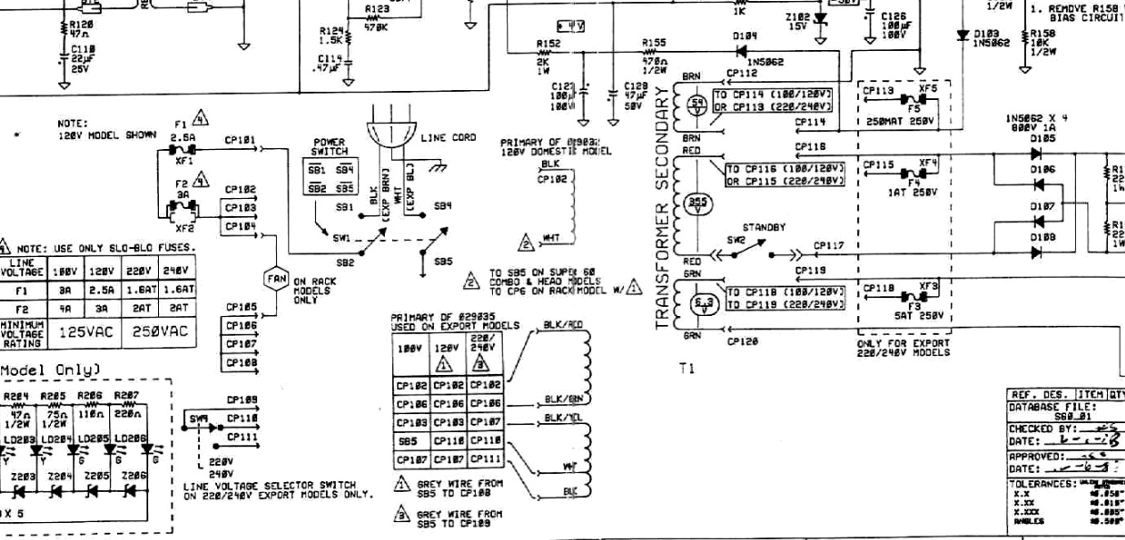
My interpretation is that you are correct about the black and white wires from the power cord going to the top terminals on the switch. The terminal below the black wire should go to interconnect CP101 that is connected to a fuse (XF1).
On the schematic, it looks like the terminal below the white wire gets grounded. That's nuts! (Maybe my interpretation is wrong?) I would connect the terminal below the white wire directly to the white wire on the power transformer, either by crimping a connector on the white wire (if there isn't one already) or by splicing into a wire that has a connector. The black wire from the transformer should plug into a junction of some sort (CP102) that has that also has a fan connected to CP104. I don't know what any of this actually looks like. You'll just need to poke around and figure it out.
IF you have an international transformer then you're on your own.
http://schems.com/bmampscom/fender/super_60_rack.pdf
Tony,
Thank you for the reply.
This thing is domestic.
It has what I see as a typical Power transformer set up. two red high voltage taps. A black 120V tap. A White lead(neutral perhaps?), which goes to the power switch. Two Green filament taps. and two brown leads for Bias. Although I'm not sure why it has two brown wires for bias, and do I need to use both?
So I ripped every thing out of it minus the transformers.
I'm just trying to use the existing PT, if I can, to save some money, and also these ugly 80's Fender switches.
The schematic is a nightmare. I think I pretty much have it figured out. Although, I don't know why there are two fuses coming off the power transformer and the switch. Why would Fender do that? It's on the board so I don't need to use it.
I'm just trying to get a proper sequence for switch, standby, mains fuse, HT fuse, and the lamp which is a marshall style that doesn't run off the heaters. The rectifier appears to be full wave bridge so I know I'm going to have to ground one end of the HT side.
The heaters don't have a center tap so I will have to create an artificial one with the 100 Ohm resistors to ground.
Anyway, thoughts, or any input is very welcome.
Thank you,
Ed

 Topic: Fender Super 60 to Hoffman Plexi 50 Conversion (Read 12060 times)