...Wouldn't it be a good idea tho get rid of the 1.8 Ohm resistor connecting ground to the secondary HT winding? Thinking again in a perfect world it might but it already saved my as when i should not have switched it on...
I guess it got included through necessity - maybe start up surge currents are too high without some current limiting?
...I don't have any spare EL34s i am willing to put into this amp, yet, so i would like to check it - once the bias is adequate - with two tubes (push-pull), connect an 8Ohm Speaker and set it to 16 Ohm OT output. Bad Idea?
Yes, bad idea, as that would reflect a very low impedance load back to the EL34. Amp set to 4 ohms and an 8 ohm load would be better, but, as it's a 6 x EL34 arrangement, still lower than the designer intended.
Plus the HT will be rock solid, whereas guitar amps usually rely on sag at high power outputs to keep the stress on the power tubes within acceptable limits.
Point being that it should be ok at idle (assuming that the bias can be set suitably) and lower power output levels, just don't push it to high power output, and certainly don't crank it.
...I have EL34's pin 1 and 8 connected and going to ground via a 2 Ohm resitor. Should Pin 1 go to ground directly?
Ideally yes, but 2 ohms is negligible. But the schematic shows 68 or 22 ohm resistors between cathode and 0V, g3 direct to 0V; what's going on?
...I've read some things about the bias supply being unstable...My two amps work good...
...I seem to had no issues biasing the RFTs and Sovtek EL34s cold enough...
What plate or cathode current do the EL34s in your amps conduct at idle? I don't think that the stock bias supply is unstable, just it can be insufficient for some tubes. If it can be adjusted to a reasonable level, then there's no imperative to change anything.
Full disclosure - I've never worked on a SC 120, only a few 50 Plus. Of those, some needed a voltage doubler, others were borderline ok as stock, but I change them to a doubler anyway (unless requested not to), because if higher gm EL34 happen to be fitted later, then the bias would be inadequate.
For voltage doubler circuits, see
https://en.wikipedia.org/wiki/Voltage_doublerThe Greinacher is easy to implement as a mod, because one leg of the bias winding stays connected to chassis 0V. It's only half wave, which isn't ideal but it's not an issue in this application, as the loading is very low.
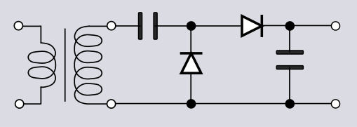
Note the Valve Wizard schematic for the appropriate orientation of polarised ecaps, as it's confusing / non-intuitive.
The full wave Delon circuit is theoretically better, but a little more involved and so more work and complexity to implement it as a mod.

 Topic: Sound City 120 is in a bad way (Read 21653 times)