Welcome To the Hoffman Amplifiers Forum

September 06, 2025, 04:54:23 pm
guest image
Welcome, Guest. Please login or register.
-User Name
-Password


Hoffman Amps Forum image Author Topic: Repair Project: 70s Earth Super Guitar G-2000  (Read 6945 times)

0 Members and 1 Guest are viewing this topic.

Offline winterturtle

  • Level 1
  • *
  • Posts: 65
  • I love Tube amps
Hoffman Amps Forum image
Repair Project: 70s Earth Super Guitar G-2000
« on: December 11, 2023, 03:58:00 pm »
I love the Earth Super Bass B-2000 I got my mits on a year or two prior -- and had an opportunity to pickup a (admittedly roach'd) white naugahyde Super Guitar G-2000 combo (the G-22 rear-label for the 2x12 config) that's near or past death. I've done a survey on its condition and would love to hear opinions on what I am missing or misinterpreting.

***Intending to come back and post some images to support - need to relearn that process.

Sorry for longwindedness -- I've tried to do my due diligence. I am a repair hobbyist - but know and practice safe work around voltage & caps. I run a limiter & am planning to add a variac this round for some added caution...

So the unit was listed as having bad tubes. I assumed it would be much more when buying.


Immediate visual inspection:
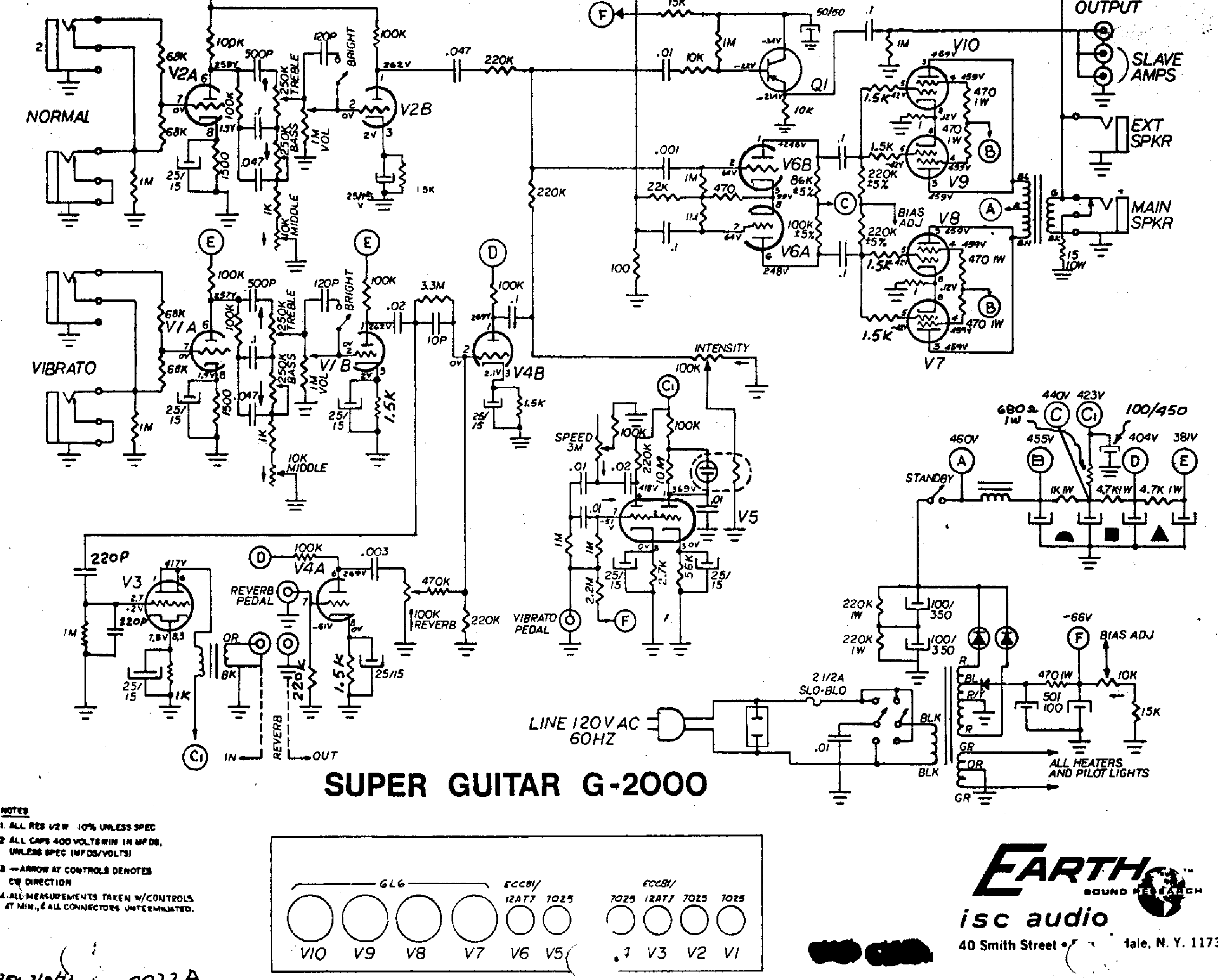
Power valve V8 has the white hazing rather than normal silver so assuming she ded
Power valve V10 has a little brown burnt spot that won't wipe / appears inside? No other visual evidence here.
2-prong cord with many visible breaks
Service receptacle on rear broken out - floating in chassis with exposed solder joints
Fuse holder looks like it was removed by a heavily intoxicated beaver - evidence old fuse holder leads were spun together =(

Pulled the chassis, continued visual inspection:
1ohm 1W resistor in series from V10/V9 cathode to ground moderately burnt, shows some cracks -- The one for V8/V7 visually OK.
Heater wire from V7 to V8 has a strange burnt spot mid run - never seen such a thing...
The single diode off the amp-side of power transformer for bias supply had what may have been some soot on it. Body looks ok.
2 VERY burnt resistors in the filter cap region.
    The 1K 1W resistor from transformer power to the first can cap terminal was so scorched only the silver line was visible and I thought it was a big diode at first.
    The 680ohm 1W sending 423v to V3 & V5 plates was blown in half. A little damage to wires below but not burnt through entirely.
Visible electrolyte vomit from:
    one of the 100/350 incoming from rectifier to PT
    also from 100/450 just before C1 in the drawing
    not externally visible but several others appear swollen as they do...

Items showing previous 'fingees in my chassis'
    Some input resistors appear to be carbon film / updated from solid carbon (the resistor looking ones, not the old school cylinders)
    Some other reverb/preamp/trem area resistors also updated
    V10 & V8 grid stoppers also updated to film - other two appear original? WEIRD
    Perhaps some other shoddy (IMHO) soldering decisions; unsure if factory...

I'm not at the point where my knowledge of these systems allows me to have a quick cause and effect vision. I am trying to think through the normal -- 'resistors burn up for a reason' and try to probe and explain the failures before going too far.

Causes?
    I know a burnt tube can cause other failures. Could V8 losing vacuum cause the V10/9 cathode resistor to fail? and the heater circuit wire? Perhaps?
    Maybe the big 100/450 cap failing to ground would burn those resistors in the manner I am seeing? I have not isolated / tested for a short to ground yet -- I read that is somewhat rare.
    I bet there's something(s) I'm not seeing!

My Project Plan with Current Information
- Fixing of the chassis / install a new fuse holder
- 3-prong & remove the so called 'death cap'
- Replace the damaged heater wire (need to check my gage still)
- I plan to swap all the electrolytics - with the visible leak on some and original appearance, why not?
- replace smoked 3 resistors plus the other cathode resistor for good measure
- nice thorough clean of all pots, switches, jacks, tube sockets
- install preamp tubes (any reason to check / suspect bad? Appear visibly OK. I can install in another amp but lack a tester =/ )
- put on a variac & limiter -- slowly dial up watching current w/o power tubes installed. Check bias supply & the voltages from the filter caps / supply voltages

If all is well...
New power tubes
Check bias (I need to brush up on process here)
Probably update all the grid stoppers for consistency
check the other changed components to see if they are as anticipated

That's it! I'm really just trying to get the unit working as designed to be my primary amp with the boys. I love the weird aesthetic and have always loved the sound & headroom of a Twin Reverb. As long as the little venue sound guys don't see it and shoot me in the parking lot I think I'll be perfect!

Any opinions, items to check, corrections, etc -- Super Appreciated! =)

Offline winterturtle

  • Level 1
  • *
  • Posts: 65
  • I love Tube amps
Hoffman Amps Forum image
Re: Repair Project: 70s Earth Super Guitar G-2000
« Reply #1 on: December 11, 2023, 04:18:44 pm »
I am clunky with the images - won't try to embed in the broader post yet...

This is one of the cathode resistor looking crunchy

one of both the burnt resistors near the filter caps -- yellow jumper hooks for focus

one of the belching cap by the exploded resistor

Offline winterturtle

  • Level 1
  • *
  • Posts: 65
  • I love Tube amps
Hoffman Amps Forum image
Re: Repair Project: 70s Earth Super Guitar G-2000
« Reply #2 on: December 11, 2023, 04:21:39 pm »
overall chassis

insane fuse bypass

blown tube & others

Offline winterturtle

  • Level 1
  • *
  • Posts: 65
  • I love Tube amps
Hoffman Amps Forum image
Re: Repair Project: 70s Earth Super Guitar G-2000
« Reply #3 on: December 11, 2023, 04:22:47 pm »
bad-bad filter cap

new addition!

Family photo =)

Offline sluckey

  • Level 5
  • *******
  • Posts: 5075
    • Sluckey Amps
Hoffman Amps Forum image
Re: Repair Project: 70s Earth Super Guitar G-2000
« Reply #4 on: December 11, 2023, 04:34:06 pm »
Fender twin reverb dressed up in a Kustom suit! Very much worth fixing.
A schematic, layout, and hi-rez pics are very useful for troubleshooting your amp. Don't wait to be asked. JUST DO IT!

Offline winterturtle

  • Level 1
  • *
  • Posts: 65
  • I love Tube amps
Hoffman Amps Forum image
Re: Repair Project: 70s Earth Super Guitar G-2000
« Reply #5 on: December 11, 2023, 04:47:08 pm »
Fender twin reverb dressed up in a Kustom suit! Very much worth fixing.

Couldn't agree more! Was looking casually for a gilttery Kustom when I found the turquoise B-2000 and fell in love. Tube naugahyde? Yes pah-leeze!

Preparing to pick this baby up I was looking for a schematic -- and an hour before driving I was shocked to discover she was on the internet! And the PO found her IN THE TRASH!!! (Look at the very bottom - http://www.pedalhaven.com/history-earth-sound-research-amplifiers/ )

I felt kinda funny about paying for a dumpster find but to be honest I would do the same if I found something cool. Very happy with the acquisition! =P

Offline winterturtle

  • Level 1
  • *
  • Posts: 65
  • I love Tube amps
Hoffman Amps Forum image
Re: Repair Project: 70s Earth Super Guitar G-2000
« Reply #6 on: December 12, 2023, 03:54:08 pm »
I've checked the capacitors downstream and though the values seem off (little amazon uF tester) they are not shorted to ground.

I am nervous I haven't identified a root cause on the (I think are called) 'dropping resistor' failures... highlighted in blue here.

I have similar nerves on the V10/9 cathode resistor that burned. V8 is the 'lost vacuum' tube - would that cause a failure like in red?

Offline glass54

  • Level 2
  • **
  • Posts: 366
  • I love Tube amps
Hoffman Amps Forum image
Re: Repair Project: 70s Earth Super Guitar G-2000
« Reply #7 on: December 12, 2023, 04:37:09 pm »
Dear W/Turtle
Quote
I am nervous I haven't identified a root cause on the (I think are called) 'dropping resistor' failures... highlighted in blue here.
Do not worry, the carbon resistors are a little "worn out"( Like some of us  :laugh:)
Consider this an opportunity! Replace your Dropping resistors with 2W or 3W Metal Oxide types (Doug should be able to help you there)
Also I would replace all 4 G2 resistors originally 470R 1W probably Carbon, with 470R 2W Metal Oxide types.
There may be other resistors on Plates, eg PI (82k and 100k) worth upgrading to Metal Oxide 1W type esp if you want to keep the amplifier
ie good investment and high reliability.
Kind regards,
Mirek
"To measure is to know"

Offline winterturtle

  • Level 1
  • *
  • Posts: 65
  • I love Tube amps
Hoffman Amps Forum image
Re: Repair Project: 70s Earth Super Guitar G-2000
« Reply #8 on: December 12, 2023, 07:52:36 pm »
Thanks Mirek! Peace of mind for me -- what do you think on the cathode resistors? They're 1w 1r carbon comp from factory. I have heard people talk about them acting kinda like a fuse - so to stick to the 1w 1r - but subbing in MO or MF.

Speaking of ... risk to power transformer I'm more than a little worried on that note. I hope the bypassed mains fuse + this weird melted spot in the heater wire doesn't spell for PowerTrans replacement =/ -- seems the way to test a power transformer is to desolder then add (fused lol) mains and test the voltage outputs? Seems laborious =P

Offline glass54

  • Level 2
  • **
  • Posts: 366
  • I love Tube amps
Hoffman Amps Forum image
Re: Repair Project: 70s Earth Super Guitar G-2000
« Reply #9 on: December 12, 2023, 09:46:46 pm »
Hi W/T,
If you study Doug's AB763 files, https://el34world.com/Hoffman/files/Hoffman_AB763_2.pdf, you will note that the Dropping Resistors are 3W  :icon_biggrin: You don't necessarily need 3W for node D and E (1W is sufficient). Also if you look at R54 and R55, the 470R are indicated as 3 Watt. I have in the past used both 2 Watt Metal Oxide or 5 Watt Wirewound depending on what I had on hand but Never CARBON 1W!! They are a source of failure (climb forever upwards in value until "Boom" ie O/C)
If you were to look at Sluckeys (very good) Pheonix assembly drawing, you would note that Steve makes extensive use of 3W (Probably Metal Oxide) resistors in those locations as well.
Personally I only stock 1W, 2W, 3W Metal Oxide resistors because in reasonable quantities, they are cheap in Aussie and a few values of 5W wirewounds. I use 400mW elsewhere, esp for grid resistors. (Doug's resistors https://hoffmanamps.com/MyStore/perlshop.cgi?ACTION=enter&template&thispage=Resistors&ORDER_ID=!ORDERID!
To you question of Cathode resistors, really anything you have on Hand  :laugh: Think about the Maths, P=IxIxR R=1R, I=50mA, 100mA max?
1W is fine  :icon_biggrin:
Marshall 9000 series Tube Power Amps used 1R 0.5W (R3, R4, R5 and R6 on drawing 9100-61-02 PSU PCB)  on the Output Cathodes which often failed. Probably due to their design or unreliable tubes??
"Weird melted spot" is that melted insulation from proximity of soldering iron?? You may want to inspect further and enlighten us (good Carbon deposit  :l2:) Heater Wires are usuall quite toug and well rated.
For personal safety reasons, you should not be running an amp with bypassed fuses  :w2:
At least have a Residual Current Device in you mains supply and probably the "in line lamp" popular with our colleagues.
Anyway , at the end of the day take good notes from our experienced colleagues and enjoy your amp. I say again, if you intend to keep the amp, go the extra mile, make it reliable and enjoyable.
Kind regards
Mirek
« Last Edit: December 12, 2023, 09:51:29 pm by glass54 »
"To measure is to know"

Offline winterturtle

  • Level 1
  • *
  • Posts: 65
  • I love Tube amps
Hoffman Amps Forum image
Re: Repair Project: 70s Earth Super Guitar G-2000
« Reply #10 on: December 13, 2023, 05:52:00 am »
Hi W/T,
If you study Doug's AB763 files, https://el34world.com/Hoffman/files/Hoffman_AB763_2.pdf, you will note that the Dropping Resistors are 3W  :icon_biggrin: You don't necessarily need 3W for node D and E (1W is sufficient). Also if you look at R54 and R55, the 470R are indicated as 3 Watt. I have in the past used both 2 Watt Metal Oxide or 5 Watt Wirewound depending on what I had on hand but Never CARBON 1W!! They are a source of failure (climb forever upwards in value until "Boom" ie O/C)

I'm totally aligned on MO/ flameproof for the dropping. I'm anticipating 3w across the board because... why not? Reliability is indeed my goal - this one's intended as a keeper/player.

If you were to look at Sluckeys (very good) Pheonix assembly drawing, you would note that Steve makes extensive use of 3W (Probably Metal Oxide) resistors in those locations as well.
Personally I only stock 1W, 2W, 3W Metal Oxide resistors because in reasonable quantities, they are cheap in Aussie and a few values of 5W wirewounds. I use 400mW elsewhere, esp for grid resistors. (Doug's resistors https://hoffmanamps.com/MyStore/perlshop.cgi?ACTION=enter&template&thispage=Resistors&ORDER_ID=!ORDERID!

The fam's headed to FLA for the holiday so I'll be ordering to that state in the next few days - in hopes I can reinforce to the fam that I'm an oddball doing my yuletide electronics repair =P

I'm gonna spend some time with these drawing links & thanks again. Seems like an opportunity to 'stand upon the shoulders of giants' =)

To you question of Cathode resistors, really anything you have on Hand  :laugh: Think about the Maths, P=IxIxR R=1R, I=50mA, 100mA max?
1W is fine  :icon_biggrin:
Marshall 9000 series Tube Power Amps used 1R 0.5W (R3, R4, R5 and R6 on drawing 9100-61-02 PSU PCB)  on the Output Cathodes which often failed. Probably due to their design or unreliable tubes??

"Weird melted spot" is that melted insulation from proximity of soldering iron?? You may want to inspect further and enlighten us (good Carbon deposit  :l2:) Heater Wires are usuall quite toug and well rated.
For personal safety reasons, you should not be running an amp with bypassed fuses  :w2:
At least have a Residual Current Device in you mains supply and probably the "in line lamp" popular with our colleagues.
Anyway , at the end of the day take good notes from our experienced colleagues and enjoy your amp. I say again, if you intend to keep the amp, go the extra mile, make it reliable and enjoyable.
Kind regards
Mirek

Weird melt spot makes me most uncomfortable. It's well tucked below other original-looking wiring and doesn't resemble soldering iron graze -- I'll grab more pics this AM when at the desk.

Also yes - I have a lightbulb limiter & the previous owner is the one who appears to have bypassed the fuse. I may be a bit unconventional - but if a fuse blows I will never in any system bypass it myself - unless I need to stay warm by a (toxic) bonfire =P PO states he plugged the unit in (he'd already found in the trash - so we're potentially snowballing issues here...) and when it began producing smoke he quickly unplugged. Ruh roh raggy... I'd hoped smoke was resistors  :BangHead:

I have all the tubes out - will remove the pilot light - and see if I have a short to ground and-or health resistance in the heater circuit. Maybe I can perform other checks?

Offline winterturtle

  • Level 1
  • *
  • Posts: 65
  • I love Tube amps
Hoffman Amps Forum image
Re: Repair Project: 70s Earth Super Guitar G-2000
« Reply #11 on: December 13, 2023, 07:48:49 am »
Oh man, I think I am $#*%-ed

Added pics of the weird heater line eruption... & the strange drop looking stuff on the green PT output for the heaters...

I have .1ohm across the two legs of the heater circuit with all tubes and pilot removed.

I also have .1ohm from heater circuit to ground/chassis.

Dead power transformer?  :help:

Offline sluckey

  • Level 5
  • *******
  • Posts: 5075
    • Sluckey Amps
Hoffman Amps Forum image
Re: Repair Project: 70s Earth Super Guitar G-2000
« Reply #12 on: December 13, 2023, 08:29:51 am »
The resistanceof the 6.3v heater winding is supposed to be very low.
A schematic, layout, and hi-rez pics are very useful for troubleshooting your amp. Don't wait to be asked. JUST DO IT!

Offline winterturtle

  • Level 1
  • *
  • Posts: 65
  • I love Tube amps
Hoffman Amps Forum image
Re: Repair Project: 70s Earth Super Guitar G-2000
« Reply #13 on: December 13, 2023, 09:23:31 am »
I had interpreted .1ohm path from either side of the heater winding to chassis ground to be -- a sign of a short in the transformer or the circuit (tubes / pilot removed)

THEN I WENT BACK TO THE SCHEMATIC (oh bother) & realized there is indeed a center tap on the heater line. Foot-to-mouth lol.

Perhaps as Mirek said ' DO NOT WORRY ' is the best advice for me haha. Fix what I've identified, power up gently on a limiter and see where I am =)

Offline winterturtle

  • Level 1
  • *
  • Posts: 65
  • I love Tube amps
Hoffman Amps Forum image
Re: Repair Project: 70s Earth Super Guitar G-2000
« Reply #14 on: December 14, 2023, 04:22:43 pm »
Getting my big ole parts order in - in hopes I have a project for gramma's house time =)

The amp as built has 150uF/300v filter caps installed right after the rectifier diodes... Drawing has 100uF/350v called out though. The B-2000 I have is the same discrepancy drawing v as-built.

100uF/350v is available on this here fine website but not a 150uF... I've always used the wisdom of 'go up, not down' with caps.

Think 100uF/350v is legit? Drawing v as-built makes me wonder if that was availability - or a revision down the road when they ran into issues  :dontknow:

Offline sluckey

  • Level 5
  • *******
  • Posts: 5075
    • Sluckey Amps
Hoffman Amps Forum image
Re: Repair Project: 70s Earth Super Guitar G-2000
« Reply #15 on: December 14, 2023, 05:02:56 pm »
Fender Twin Reverb used 70µF/350V. The later 100W version used 100µF/350V. When 70µF became scarce, everyone switched to 100µF. I would use 100µF/350V.
A schematic, layout, and hi-rez pics are very useful for troubleshooting your amp. Don't wait to be asked. JUST DO IT!

Offline winterturtle

  • Level 1
  • *
  • Posts: 65
  • I love Tube amps
Hoffman Amps Forum image
Re: Repair Project: 70s Earth Super Guitar G-2000
« Reply #16 on: December 14, 2023, 05:14:23 pm »
Thank you friend -- I got myself spooked looking at the voltage on the line vs the ratings.

So it seems - two caps of equal value share the voltage equally between them so using the two 100/350 means the rating of that assembly is 700v (w/ line at 460v.) Then the assembly's capacitance is half so 50uF.

NGL I don't understand how the resistors figure in the mix - but at least so far I think I'm keeping up!

Offline PRR

  • Level 5
  • *******
  • Posts: 17082
  • Maine USA
Hoffman Amps Forum image
Re: Repair Project: 70s Earth Super Guitar G-2000
« Reply #17 on: December 14, 2023, 05:19:11 pm »
> two caps of equal value share the voltage equally between them .... I don't understand how the resistors figure

You are almost there. Two ideal caps are NOT sure to split equally because they are infinite resistance at DC. In reality the least-leaky cap takes most of the voltage. The higher voltage "may" increase leakage and improve balance. "Added leakage" like large resistors does this better.

Offline winterturtle

  • Level 1
  • *
  • Posts: 65
  • I love Tube amps
Hoffman Amps Forum image
Re: Repair Project: 70s Earth Super Guitar G-2000
« Reply #18 on: December 14, 2023, 06:11:52 pm »
So the intent of the resistors -- is to provide some balancing action between the two caps? I think that's the idea?


I'm now kinda grappling with the 680r 1w resistor connecting to C1 -- looking for a 680r 2w rated 500v plus working but that seems to not be a thing. Checked the AB763 drawing I'm jumping between & it seems my unit runs through this 680r for 423v before heading to plates on reverb and trem... while the AB763 sends 438v (458v?) there right off the choke.

I'm not landing at even a question ha - may be a brain break then decide if I wanna find a combo to run in parallel...

Offline PRR

  • Level 5
  • *******
  • Posts: 17082
  • Maine USA
Hoffman Amps Forum image
Re: Repair Project: 70s Earth Super Guitar G-2000
« Reply #19 on: December 14, 2023, 06:49:32 pm »
> looking for a 680r 2w rated 500v

It does not know any 500V. Bird on a wire.

Offline sluckey

  • Level 5
  • *******
  • Posts: 5075
    • Sluckey Amps
Hoffman Amps Forum image
Re: Repair Project: 70s Earth Super Guitar G-2000
« Reply #20 on: December 14, 2023, 06:50:59 pm »
I'm now kinda grappling with the 680r 1w resistor connecting to C1 -- looking for a 680r 2w rated 500v
Forget about the 500V. Just use this 2 watt metal oxide. It's fine.

     https://www.tubesandmore.com/products/resistors-2-watt-metal-oxide-power

BTW, that 100µF cap connected to C1 is drawn backwards on the schematic.
A schematic, layout, and hi-rez pics are very useful for troubleshooting your amp. Don't wait to be asked. JUST DO IT!

Offline winterturtle

  • Level 1
  • *
  • Posts: 65
  • I love Tube amps
Hoffman Amps Forum image
Re: Repair Project: 70s Earth Super Guitar G-2000
« Reply #21 on: December 23, 2023, 01:48:06 pm »
Quote
BTW, that 100µF cap connected to C1 is drawn backwards on the schematic.

OMG haha what a good eye! I'm gonna be marking mine up as a final 'as modified'

I've made it this far. Hoping my ditching the can cap and adding terminal strips doesn't make me a hum factory!

Double checking the wiring tonight then gonna break out the limiter and variac. Always a tense phase to be at!

Offline winterturtle

  • Level 1
  • *
  • Posts: 65
  • I love Tube amps
Hoffman Amps Forum image
Re: Repair Project: 70s Earth Super Guitar G-2000
« Reply #22 on: December 23, 2023, 02:06:33 pm »
I had in mind powering the unit up with only preamp tubes and checking the voltages in the power supply to see if they are ballpark & good heater voltage. Then set the negative voltage for the bias before trying with power valves in...

Noticed the -66v in the drawing is for the trem F connection. Does it make sense to start at -52v a la a Twin Reverb?

Also - is a shorted preamp tube a concern? With the previous damage I kinda see everything as risky haha.
« Last Edit: December 23, 2023, 02:33:15 pm by winterturtle »

Offline winterturtle

  • Level 1
  • *
  • Posts: 65
  • I love Tube amps
Hoffman Amps Forum image
Re: Repair Project: 70s Earth Super Guitar G-2000
« Reply #23 on: December 23, 2023, 04:24:00 pm »
Had another thought - to add the new terminal strips I added a wire where one wasn't previously needed. I used a 20ga stranded but am now wondering if I undersized. Lotta power here so thinking maybe I kinda messed up this detail. The knowledgeable here think this is ok or undersized? =/
« Last Edit: December 23, 2023, 04:34:45 pm by winterturtle »

Offline sluckey

  • Level 5
  • *******
  • Posts: 5075
    • Sluckey Amps
Hoffman Amps Forum image
Re: Repair Project: 70s Earth Super Guitar G-2000
« Reply #24 on: December 23, 2023, 05:18:32 pm »
That single terminal lug seems useless to me. You could have easily connected those two wires directly to the terminal where the cap is connected.
A schematic, layout, and hi-rez pics are very useful for troubleshooting your amp. Don't wait to be asked. JUST DO IT!

Offline winterturtle

  • Level 1
  • *
  • Posts: 65
  • I love Tube amps
Hoffman Amps Forum image
Re: Repair Project: 70s Earth Super Guitar G-2000
« Reply #25 on: December 23, 2023, 06:13:38 pm »
I definitely had a 'oh man now that seems obvious' moment and ran to see - theres no additional slack available on the choke wire so im about an inch or so short =/

But yeah that single terminal is definitely vestigial at this point  :laugh:

Offline sluckey

  • Level 5
  • *******
  • Posts: 5075
    • Sluckey Amps
Hoffman Amps Forum image
Re: Repair Project: 70s Earth Super Guitar G-2000
« Reply #26 on: December 23, 2023, 06:58:18 pm »
theres no additional slack available on the choke wire so im about an inch or so short =/
Makes sense now.
A schematic, layout, and hi-rez pics are very useful for troubleshooting your amp. Don't wait to be asked. JUST DO IT!

Offline PRR

  • Level 5
  • *******
  • Posts: 17082
  • Maine USA
Hoffman Amps Forum image
Re: Repair Project: 70s Earth Super Guitar G-2000
« Reply #27 on: December 24, 2023, 12:19:40 am »
> I used a 20ga stranded but am now wondering if I undersized. Lotta power here so thinking

Look up the ampacity of single #20 wire.

https://www.engineeringtoolbox.com/wire-gauges-d_419.html

Looks like 6 AMPS ?

Read a 6L6 datasheet. What the most screen current you see? Adjust for number of 6L6es. Add a few mA for little bottles. Is there any way it gets to even 100mA, 0.01 Amps, 1/60th the rating for #20 wire?

Offline winterturtle

  • Level 1
  • *
  • Posts: 65
  • I love Tube amps
Hoffman Amps Forum image
Re: Repair Project: 70s Earth Super Guitar G-2000
« Reply #28 on: December 24, 2023, 09:47:37 am »
I'm disproving the 'no stupid questions' adage haha.

Ok yeah so DC voltage and there's plates + capacitors to ground downstream and the caps only transfer AC. I found a typical value of 1.2mA for a 12ax7. Driving 12 plates together should be .0144A - so WAY below to your point - and thank you!

I had it in mind that higher voltage would mean less amperage carrying capacity - now seeing thats incorrect. I need to spend some time with a pad of paper playing with some V=IR to use math to visualize this. The concept of high voltage transmission lines being able to move massive amounts of energy on small wires has to be this same 'theory.'

I may get my confidence up to try this system today. I've double checked my wiring and think it's right. Since I dont have a tube tester I may use all new preamp tubes - in case I have a short or something in play.

I appreciate the help. I can solder and swap parts... I get the basic theory of operation for simple diagnostic... but I am definitely missing a lot of the foundational math and concepts underlying the systems =)

Offline PRR

  • Level 5
  • *******
  • Posts: 17082
  • Maine USA
Hoffman Amps Forum image
Re: Repair Project: 70s Earth Super Guitar G-2000
« Reply #29 on: December 24, 2023, 05:10:50 pm »
Voltage means thick rubber (Air, plastic, porcelain...)

Current means thick Copper (Aluminum, iron wire, sea water...)

Unless your PVC is smoking, voltage is not a limit.

POWER is Voltage times current. I could power my house with 120V 200 Amps or 20,000V 1.2 Amps. The 10 mile run to the dam generator would be VERY expensive in copper at 120V 200A, but the insulation could be negligible. OTOH the 1.2 Amps at 20,000V can be run on very skinny even "bad" metal; in fact they run 3/16" Steel to resist fallen branches.

Offline winterturtle

  • Level 1
  • *
  • Posts: 65
  • I love Tube amps
Hoffman Amps Forum image
Re: Repair Project: 70s Earth Super Guitar G-2000
« Reply #30 on: January 01, 2024, 02:56:21 pm »
Happy new year folks! What a whirlwind the holidays are =)

I have the unit running, biased up & it seems pretty happy with a couple exceptions. New power tubes seem happy - when 2 or 3 of the preamp tubes were loudly microphonic I went ahead and swapped all for new there too.

I did a run through the overall and found a number of out of spec resistors so have an order coming at Doug tomorrow morning =) I've settled on metal oxide for all the power then sticking with carbon comp for the rest.

The V3 in the reverb gets pretty darn hot - hotter than I've ever noticed a 12A-tube get. I saw some internet chatter around swapping the cathode-s resistor from a 1k to a 2.2k or 2.7k - which also gets closer to Twin spec so seems appropriate. The verb sounds nice and strong after some jack cleaning...

Trem is strange. It sticks on -- and jamming my shorted RCA in an out a few times usually stops it. Gonna swap the RCA; I get 2.72Mohms across the existing when it should be open, not sure if that is or is not normal haha. Turning the trem on also gives a big gain drop -- planning to swap the bug on the assumption that's the issue there. The speed is also very non-linear by which I mean it's SLOOOOOOOW through most of the throw of the control then pretty suddenly jumps up to super fast. A good range but odd. I'm going ahead and changing the caps in the circuit (along with most of the resistors based on their readings...) Maybe the trem will be legit with nearly all new parts haha.

The issue I am most concerned about is a lot of noise in the treble. All the pots came clean with some deoxit and working -- and the volume itself doesn't contribute to a bad noise floor. All the controls at 10 with treble on 0 and it's crickets.

The treble on the other hand - gives a ton of white noise. It's not horrible but with this level of work I have it in my head I want it as good as it'll get. It sounds like a white noise - not like interference or power hum I have heard before. Normal channel and vibrato channel act the same - so I am thinking it's not upstream preamp.

I've read a few conversations talking about the 100k resistors in the preamp being known for this kind of noise - but didn't get a lot of the 'why' perspective. I'm also planning to swap the caps in the tone stacks which I hope may help - one of each is ceramic and one of each has an oily appearance and the surface coating is cracking...

Any experience or ideas around a quiet amp - that only really has a noise issue when one of the treble controls is up?

Offline winterturtle

  • Level 1
  • *
  • Posts: 65
  • I love Tube amps
Hoffman Amps Forum image
Re: Repair Project: 70s Earth Super Guitar G-2000
« Reply #31 on: January 08, 2024, 06:20:55 pm »
Taking first things first, I'm replacing the out of spec resistors I've found so far and to avoid multiple heat cycles figured it made sense to do some 'while I'm in there' replacements of some coupling / tone stack caps. In the values I need it seems silve mica & ceramic disc are the only options & consensus was ceramic values can be kinda off in operation - paraphrasing and 100% still learning...

I ordered and just today received a few of the silver mica from AES -- labelled with the values and only 'SM' as the identifier. https://www.tubesandmore.com/products/capacitor-500v-silver-mica-5

Well low and behold I'm on the old ewe-toob and one of the, seemingly well respected, gents who posts a lot of this kind of content encounters an issue caused by SM caps. Goes on to describe repeated bad experiences & returns of amps he's worked on so never uses the SMs. I google and find people discussing how they also have had bad experiences... They use CERAMIC instead!

I realize cap material discussion involves preference. I don't think I will be the type of ear to really pick up on 'mojo' and whatnot... in values like 10pF, 120pF, 220pF, & 500pF with limited availability in Mallory 150 style, what's this group like to use if the focus is low noise & reliability?

Offline PRR

  • Level 5
  • *******
  • Posts: 17082
  • Maine USA
« Last Edit: January 08, 2024, 07:57:40 pm by PRR »


Choose a link from the
Hoffman Amplifiers parts catalog
Mobile Device
Catalog Link
Yard Sale
Discontinued
Misc. Hardware
What's New Board Building
 Parts
Amp trim
Handles
Lamps
Diodes
Hoffman Turret
 Boards
Channel
Switching
Resistors Fender Eyelet
 Boards
Screws/Nuts
Washers
Jacks/Plugs
Connectors
Misc Eyelet
Boards
Tools
Capacitors Custom Boards
Tubes
Valves
Pots
Knobs
Fuses/Cords Chassis
Tube
Sockets
Switches Wire
Cable


Handy Links
Tube Amp Library
Tube Amp
Schematics library
Design a custom Eyelet or
Turret Board
DIY Layout Creator
File analyzer program
DIY Layout Creator
File library
Transformer Wiring
Diagrams
Hoffmanamps
Facebook page
Hoffman Amplifiers
Discount Program