Welcome To the Hoffman Amplifiers Forum

September 07, 2025, 03:40:35 pm
guest image
Welcome, Guest. Please login or register.
-User Name
-Password


Hoffman Amps Forum image Author Topic: A(nother) 15 Watt Amplifier  (Read 8307 times)

0 Members and 1 Guest are viewing this topic.

Offline darryl

  • Level 2
  • **
  • Posts: 246
    • ValveTone Amplification
Hoffman Amps Forum image
A(nother) 15 Watt Amplifier
« on: April 30, 2011, 10:47:46 pm »
I have been asked to build a new amplifier, so I thought I might post the details of its construction.

The specification was as follows: single channel but with tonestack switching options, 2 x EL84 output valves for a nominal 15 watts. This was essentially identical to one of my earlier designs, so there was a reduced probability of embarrassing meltdowns.

My construction methods were described in some detail in an earlier build description: http://www.el34world.com/Forum/index.php?topic=9027.0 You cannot teach an old dog new tricks, so this project will use very similar methods.

Construction was on a small aluminium pan chassis. The component layout on the chassis top surface was drawn to fit three transformers, the two output valves, and two small-signal valves. A faceplate was already available, so it was used as a template for marking out the front panel. An assortment of drills, files and chassis punches were used to prepare the chassis - surprisingly no blood was lost during this process.


The construction method was point-to-point, using tagstrips. Once the valve sockets had been installed, the tagstrips were next.


I do not use a star grounding scheme, instead using a ground plane method. The tagstrips are riveted into the chassis, but one ground tag in each row is attached much more securely with an M3 machine screw, a nut, and two shakeproof washers. Tinned copper wire is then run from this ground tag and soldered to the other riveted tags, so a secure ground is established at each tag.

Once the tagstrips were in, the twisted pair heater wiring was fitted, and other hardware installed - including rubber grommets where wires would pass through the chassis, the IEC power socket, and the power switch. I often use a rear-mounted power switch to confine the 240 volt AC power to one back corner of the chassis - and because my front panels seldom have space for an extra switch.

To be continued . . .  :icon_biggrin:

Offline Cups

  • Level 2
  • **
  • Posts: 102
Hoffman Amps Forum image
Re: A(nother) 15 Watt Amplifier
« Reply #1 on: May 01, 2011, 05:22:47 pm »
Eagerly waiting.  :icon_biggrin:

Offline darryl

  • Level 2
  • **
  • Posts: 246
    • ValveTone Amplification
Hoffman Amps Forum image
Re: A(nother) 15 Watt Amplifier
« Reply #2 on: May 01, 2011, 08:36:11 pm »
Transformers were next. As I have discussed before, "real" valve amplifier transformers are quite expensive here in Australia, so local builders tend to use non-standard configurations:


As with most of my amplifiers, the plate supply was provided by an off-the-shelf low voltage transformer and a voltage multiplying rectifier/filter. The larger of the two power transformers is 56VAC @ 2.4A, and is used here with a voltage quadrupler.

Theoretical DC output is 56 x 1.4 x 4 = 314 volts.    Theoretical maximum current is 2.4 ÷ (1.4 x 4) = 428mA.

The smaller power transformer is 7VAC @ 4A. It supplies the valve heaters, through a dropping resistor.

The output transformer was originally designed as a public address line transformer, but it works very effectively in guitar amplifiers using push-pull pairs of output valves such as EL84's or 6BM8's. A detailed analysis of this transformer is available here: http://home.alphalink.com.au/~cambie/6AN8amp/M1115.htm

There are exposed solder tags on two of the transformers ( not visible in the above picture ). These were shrouded with heatshrink tubing.

Offline darryl

  • Level 2
  • **
  • Posts: 246
    • ValveTone Amplification
Hoffman Amps Forum image
Re: A(nother) 15 Watt Amplifier
« Reply #3 on: May 02, 2011, 04:57:05 am »
Next, the transformer leads were terminated under-chassis. The terminations carrying 240 volt AC power were covered with heatshrink tubing.


Most of the power supply components were installed next, including the voltage quadrupler capacitors and diodes. Some of the leads and smaller components around the output valve sockets were next, followed by two extra pieces of tagstrip on the back panel. One of these was to support a resistor and capacitor which made up the output stage conjunctive filter. The speaker socket was also fitted at this stage.

Further progress, with almost all components associated with the output stage and phase splitter installed:


The master volume potentiometer was temporarily fitted, so shielded lead could be run from tags near the phase splitter.

More to come . . .  :icon_biggrin:

Offline Fresh_Start

  • Level 4
  • *****
  • Posts: 2856
  • noob de Lux
Hoffman Amps Forum image
Re: A(nother) 15 Watt Amplifier
« Reply #4 on: May 02, 2011, 08:34:42 am »
That's a unique layout!  I see that you also use the lower holes in the tag strips for connection/solder points.  Those tag strips on the back wall give you a 3-dimensional approach to wiring the power tubes - I like it!

Cheers,

Chip
Quote from: jjasilli
We have proven once again no plan survives contact with the enemy, or in this case, with the amp.

Quote from: PRR
Plan to be wrong about something.

Offline LooseChange

  • SMG
  • Level 4
  • *****
  • Posts: 3511
  • Keep it greasy so it goes down easy.
    • Fix Your Darn Amps
Hoffman Amps Forum image
Re: A(nother) 15 Watt Amplifier
« Reply #5 on: May 02, 2011, 09:24:15 am »
I'm liking this... Keep the show coming.
Call me Dan
www.fydamps.com

Offline darryl

  • Level 2
  • **
  • Posts: 246
    • ValveTone Amplification
Hoffman Amps Forum image
Re: A(nother) 15 Watt Amplifier
« Reply #6 on: May 02, 2011, 10:21:55 am »
Time to look at the front end:


The face plate and potentiometers were installed together - the faceplate being held in place by the pot nuts. The front panel LED was next - it is powered from the 6.3 volt heater supply, via a dropping resistor.

Small components were installed around the preamp valve socket, before the input connector was fitted. The input socket is close to the preamp valve, so the signal path length is very short in this highly sensitive part of the circuit.

The 3-position Gain and Bright switches were installed, and connected to the appropriate points in the layout. The tonestack components were installed on a tagstrip behind the tone controls, with some components bridged between terminals on the tone pots.

To enable the required tonestack switching, the Mid pot has a DPST pull-on switch, while the Bass pot has a DPST rotary switch. The Mid pot pull-on switch is a "voice" control, simultaneously changing the treble capacitor, and the slope resistor. I have called the two options "British" and "American", because the tonestack components switch ( very approximately ) between Fender and Marshall values. These descriptions are deliberately vague - they do not necessarily make this amplifier sound like a Fender or a Marshall. The rotary switch on the Bass pot is a tonestack lift - when the bass pot is turned fully off, the tonestack is lifted above ground by a 1 meg resistor.

Maybe it's time for a circuit. Transferring this circuit from scribbles on bits of paper, to an electronic form takes me nearly as long as it takes to build an amplifier.   :sad:


Oh, Vik will be the new owner of this amplifier.   :grin:

Offline darryl

  • Level 2
  • **
  • Posts: 246
    • ValveTone Amplification
Hoffman Amps Forum image
Re: A(nother) 15 Watt Amplifier
« Reply #7 on: May 02, 2011, 10:28:09 am »
Some pictures of the complete chassis:


Fortunately my amp building skills are somewhat better than my ability with a camera.   :rolleyes:

Offline Willabe

  • Global Moderator
  • Level 5
  • ******
  • Posts: 10524
Hoffman Amps Forum image
Re: A(nother) 15 Watt Amplifier
« Reply #8 on: May 02, 2011, 11:38:06 am »
darryl,

Man you do nice work! Wow!            :bravo1:
 

        Brad       :icon_biggrin:

Offline kagliostro

  • Level 5
  • *******
  • Posts: 7739
Hoffman Amps Forum image
Re: A(nother) 15 Watt Amplifier
« Reply #9 on: May 02, 2011, 05:12:33 pm »
Truly a work of the past

congratulations for the implementation

Kagliostro
The world is a nice place if there is health and there are friends

Offline drumslinger2000

  • Level 2
  • **
  • Posts: 106
Hoffman Amps Forum image
Re: A(nother) 15 Watt Amplifier
« Reply #10 on: May 02, 2011, 05:55:08 pm »
excellent build darryl.  where did you get the face plate?

Offline andrew_k

  • Level 2
  • **
  • Posts: 103
Hoffman Amps Forum image
Re: A(nother) 15 Watt Amplifier
« Reply #11 on: May 02, 2011, 07:26:47 pm »
Love ya work as always Darryl.
Looks like you finally ran out of your stock of mustards. Is The Shed empty?

Offline darryl

  • Level 2
  • **
  • Posts: 246
    • ValveTone Amplification
Hoffman Amps Forum image
Re: A(nother) 15 Watt Amplifier
« Reply #12 on: May 02, 2011, 07:53:50 pm »
...where did you get the face plate?

I have faceplates and nameplates engraved by a local signwriting company Ace Plastic Signs. I'm sure any business with a laser engraver would be able to do something similar.


Looks like you finally ran out of your stock of mustards. Is The Shed empty?

You mean THESE mustards?   :grin:


Although I still have lots of mustards, they are not values that suit guitar amplifiers. I don't have any .022mfd, and I now have only a few .0047mfd remaining.   :sad:
« Last Edit: May 02, 2011, 07:58:26 pm by darryl »

Offline Willabe

  • Global Moderator
  • Level 5
  • ******
  • Posts: 10524
Hoffman Amps Forum image
Re: A(nother) 15 Watt Amplifier
« Reply #13 on: May 02, 2011, 09:10:00 pm »
Where in the world did you get all those?        :laugh:

Did you have a box of .022's that big?


              Brad          :icon_biggrin:

Offline darryl

  • Level 2
  • **
  • Posts: 246
    • ValveTone Amplification
Hoffman Amps Forum image
Re: A(nother) 15 Watt Amplifier
« Reply #14 on: May 02, 2011, 10:00:43 pm »
Did you have a box of .022's that big?

If only . . .  it would have bankrolled my retirement.   :icon_biggrin:

I purchased very large quantities of components in the 1970's, when many major Australian electronics manufacturers closed, due to changes in import tariffs. Fortunately, some bits stayed with me over the years, so I still owned them when I restarted building valve amps, after a 27 year break.

When I think of the stuff I did throw out though . . .  :cry:

Offline andrew_k

  • Level 2
  • **
  • Posts: 103
Hoffman Amps Forum image
Re: A(nother) 15 Watt Amplifier
« Reply #15 on: May 02, 2011, 10:45:13 pm »
Where in the world did you get all those?        :laugh:
Mustard caps were made in two factories, one of those was in Australia.  (as is my understanding from an older amp tech here in Melbourne)

Offline darryl

  • Level 2
  • **
  • Posts: 246
    • ValveTone Amplification
Hoffman Amps Forum image
Re: A(nother) 15 Watt Amplifier
« Reply #16 on: May 05, 2011, 05:14:48 am »
Power was applied to the amplifier, and there were no pyrotechnics, so time for a few voltage measurements and calculations.

First the voltage quadrupler: The theoretical output was calculated to be 314VDC. When the amplifier was first switched on, with cold valves, the B+ was 333VDC. Once the valves had warmed up, the B+ dropped to 323VDC, which is quite close to the value calculated earlier. At maximum sinewave output, the B+ was 318VDC, at maximum squarewave output, B+ was 315VDC. This demonstrates that a voltage quadrupler with suitably rated components can easily supply the B+ power requirements of a valve amplifier.

The screen supply in this amplifier has been designed to have significant "sag", to protect the screens, and to provide some compression as the amplifier is overdriven. The zero-signal screen voltage was 310VDC. At maximum sinewave output it had fallen to 283VDC, while at maximum squarewave output it was 246VDC.

The zero-signal cathode voltage was 12VDC, so the cathode current was 12 ÷ 180 = .067 Amps

The voltage drop from cathode to anode was 323 - 12 = 311

The total plate dissipation ( ignoring the minor screen dissipation ) was 311 x .067 = 20.8 watts, or 10.4 watts per valve.

Using a 400Hz sinewave and an 8-ohm load, output voltage at the onset of clipping was 11.4VAC. This equates to an output power of (11.4 x 11.4) ÷ 8 = 16 watts.

The output transformer only has a single 8-ohm secondary, but output power was also calculated for 4 and 16 ohms, despite the nominal mismatch. The amplifier delivered 13.5 watts at 4 ohms, and 12 watts at 16 ohms.

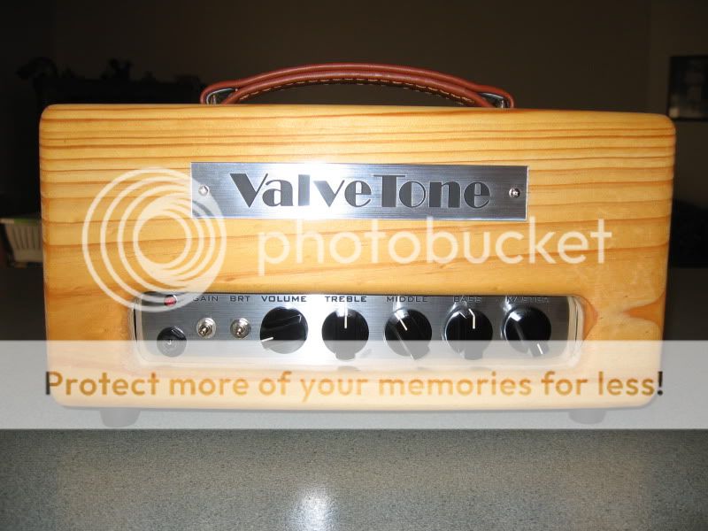
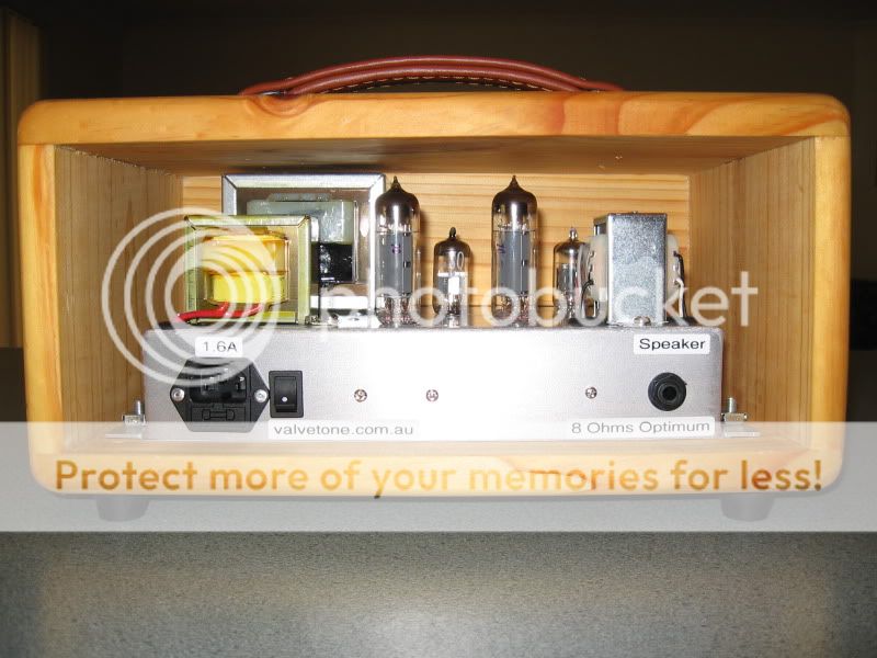
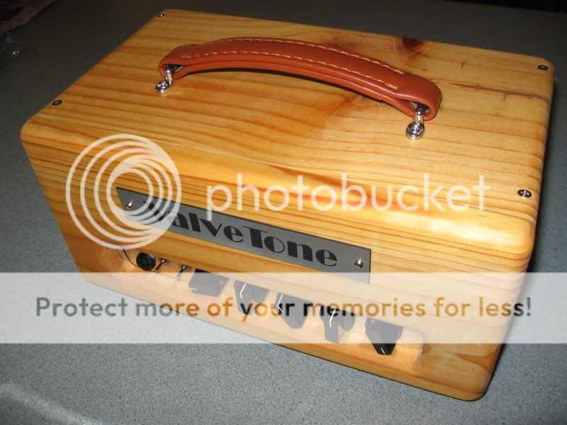
The completed chassis has now been fitted to a very basic timber headshell.


Offline tubenit

  • Global Moderator
  • Level 5
  • ******
  • Posts: 10274
  • Life is a daring adventure or nothing at all!
Hoffman Amps Forum image
Re: A(nother) 15 Watt Amplifier
« Reply #17 on: May 05, 2011, 05:58:03 am »
Really a very nicely done and beautiful build. And thank you for sharing your schematic with us.

Can you explain the zeners & the cap-resistor across the power tube plates, please?


With respect, Tubenit
« Last Edit: May 05, 2011, 06:07:33 am by tubenit »

Offline darryl

  • Level 2
  • **
  • Posts: 246
    • ValveTone Amplification
Hoffman Amps Forum image
Re: A(nother) 15 Watt Amplifier
« Reply #18 on: May 05, 2011, 10:13:25 am »
Can you explain the zeners & the cap-resistor across the power tube plates, please?

The zener diodes act as a signal clipper prior to the phase inverter. Grossly overdriving a cathodyne phase splitter can produce extremely unpleasant distortion. The zener diodes combined with the very large grid stopper resistor make the cathodyne phase splitter a much more acceptable design choice for guitar amplifiers.

The zener diode voltage is selected so that with the master volume at its maximum, the output valves can still be overdriven, to produce desirable output stage distortion. The master volume is placed after the zener clipper so the master volume can be used to limit the signal level reaching the output valves, regardless of the level produced in the preamp stages.

This does mean that as the master is turned down, the distortion being produced is from the clipper rather than the output stage, but in practice this is not an unpleasant form of power limiting. ( In my totally unbiased opinion.   :wink: )

As an historical note, I originally began using this zener diode clipper in the early 1970's, when I was building 100 and 200 watt amplifiers. These amps used four or six 6CA7 output valves, with plate voltages up to 800VDC. They used a cathodyne phase splitter followed by an extra driver stage ( a simplified Williamson circuit topology ), and without the zener diodes limiting the drive level, the output valves had a serious predisposition to self immolation.


The resistor and capacitor across the output transformer primary constitute a conjunctive filter - or corrective filter - depending on which of the ancient valve texts you read. If you Google "conjunctive filter" you will find some ( often conflicting ) opinions on their usefulness.

The original purpose of a conjunctive or corrective filter was to compensate for the rise in speaker impedance with rising frequency.  The filter component values were chosen to allow the output valve(s) to see a constant load, smoothing out the obvious harshness in cheap radios of the valve era. The conjunctive filter in a guitar amplifier is also to smooth out some harshness, but the component values are generally determined by a "try it and see" approach, rather than by a strict formula.

Offline phsyconoodler

  • SMG
  • Level 4
  • *****
  • Posts: 4679
  • honey badger don't give a ****
Hoffman Amps Forum image
Re: A(nother) 15 Watt Amplifier
« Reply #19 on: May 05, 2011, 10:20:58 am »
Your builds are a thing of beauty indeed.
  The only thing I don't like(this is not a real criticism) is the layout.i prefer a more linear layout with power section on the left or right and a board or terminal strip from one side to the other.It's way easier to build and diagnose.IMHO.
Honey badger don't give a ****

Offline tubenit

  • Global Moderator
  • Level 5
  • ******
  • Posts: 10274
  • Life is a daring adventure or nothing at all!
Hoffman Amps Forum image
Re: A(nother) 15 Watt Amplifier
« Reply #20 on: May 05, 2011, 10:41:14 am »
darryl,

THANKS for the explanation about the zeners and conjuctive filter.

After your explanation on the conjuctive filter, I remembered that some TrainWreck clones used that also but had forgotten about it.

With respect, Tubenit

Offline firemedic

  • Level 3
  • ***
  • Posts: 516
Hoffman Amps Forum image
Re: A(nother) 15 Watt Amplifier
« Reply #21 on: May 05, 2011, 10:56:12 am »
thanks a million for this post darryl. I find your unique layout very interesting; I converted a SS Kustom Contender to a SE all-tube amp but the chassis was so small there was no room for a board. I will have to replace the screw terminals I used, at some point, with something like what you have here.

Offline riffanvil

  • Level 1
  • *
  • Posts: 24
Hoffman Amps Forum image
Re: A(nother) 15 Watt Amplifier
« Reply #22 on: May 05, 2011, 01:34:29 pm »
really a nice project and build!!  i am in awe of the level of quality i keep seeing here on this board.  i liked the straight forward wooden cabinet too.  all very nice work.
Good judgement comes from experience….experience comes from bad judgement.

Offline billcreller

  • Level 4
  • *****
  • Posts: 2616
  • 1934
Hoffman Amps Forum image
Re: A(nother) 15 Watt Amplifier
« Reply #23 on: May 14, 2011, 12:56:06 am »
Very impressive build ! :icon_biggrin:
I'll never figure this out......


Choose a link from the
Hoffman Amplifiers parts catalog
Mobile Device
Catalog Link
Yard Sale
Discontinued
Misc. Hardware
What's New Board Building
 Parts
Amp trim
Handles
Lamps
Diodes
Hoffman Turret
 Boards
Channel
Switching
Resistors Fender Eyelet
 Boards
Screws/Nuts
Washers
Jacks/Plugs
Connectors
Misc Eyelet
Boards
Tools
Capacitors Custom Boards
Tubes
Valves
Pots
Knobs
Fuses/Cords Chassis
Tube
Sockets
Switches Wire
Cable


Handy Links
Tube Amp Library
Tube Amp
Schematics library
Design a custom Eyelet or
Turret Board
DIY Layout Creator
File analyzer program
DIY Layout Creator
File library
Transformer Wiring
Diagrams
Hoffmanamps
Facebook page
Hoffman Amplifiers
Discount Program