Welcome To the Hoffman Amplifiers Forum

September 07, 2025, 07:32:55 pm
guest image
Welcome, Guest. Please login or register.
-User Name
-Password


Hoffman Amps Forum image Author Topic: Old Radio Cabinet....  (Read 3469 times)

0 Members and 1 Guest are viewing this topic.

Offline Jack_Hester

  • Level 3
  • ***
  • Posts: 839
  • Greybeard
Hoffman Amps Forum image
Old Radio Cabinet....
« on: September 06, 2012, 09:04:18 am »
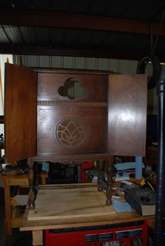
I had been admiring this radio cab, for close to three years:


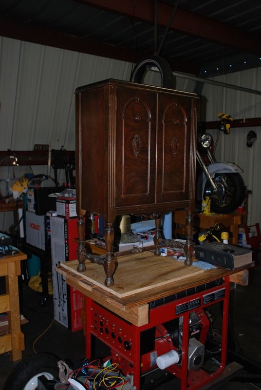
When I was looking through the pictures, I realized that I hadn't taken one of the front panel.  Will try to do so, soon.

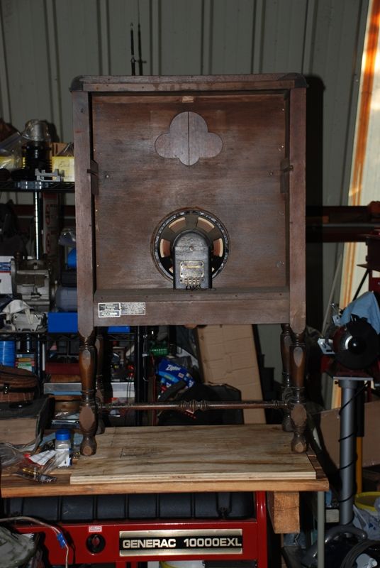
The radio cabinet was in an antique mall, about an hour and a half from home.  Get there about once a year.  And, it was always there.  The radio chassis was built in several sections, and had been cannibalized quite a bit.  Probably half of it was gone, as there were empty places on the platform that had something mounted to it.  So, I made them a very low offer, and they took it.  As this was man-day (wife had other more important things to do), I asked Don (music leader at our Church) to go with me.  We loaded it on the truck, and while we were wrapping it up and tying it down, the store clerk told me that an elderly couple had a couple boxes of tubes that they had just tried to sell, but couldn't.  I walked over to their car and looked them over.  They had about 150, by their count.  And, a rather thick book of old radio schematics.  So, we bargained and I carried those away, also.  I believe that I got more tubes than they figured.  

Anyway, to preserve the look of the front panel, I plan to only have a volume pot (with power switch), a bass pot, and a treble pot.  I've been playing around with octals for awhile, mainly because that's what I have the most of.  As I only have a few of the 12A_7 series tubes, I decided to dig through the 'non-standard' tubes that I have, to see what I can substitute in place of them.  

I've made an initial schematic, modeled after the '59 Bassman.  Not that I wanted a Bassman.  It was just a simple one to start with.  I substituted a Baxandall tone stack in place of the Fender, to eliminate the Mid pot.  I also added a Master Volume that will go on the front.  The two volume pots in the pre-amp will go on the back of the chassis.  I also added a 5G9 Tremolo to the schematic, as I wanted some form of effects built into the amp.  Those controls will go in the back, also.  I haven't assigned component labels or values, though the power supply shows labels.  I pulled it over from another drawing, and neglected to remove them.  

So, here's the first draft of the schematic:

(See rev C below)

Not a very good graphics print from ACAD, so I included a high resolution PDF print of it.  

In the drawing, I put a pot in place of the typical 220K resistors for biasing.  I figure a 500K pot to balance the bias for mismatched tubes, and a 10K to set the bias for both, down at the power supply.  I would like input as to whether anyone has done this configuration of biasing before.  And, please advise me as to a better way, if this one is impractical.  

I have a new chassis that Terry Naugler, of Seaside Music, built for me.  I had him make it to be large enough to cover the entire platform, with plenty of clearance for the pots up front.  I had to resist the urge to just fill up the chassis.  I will leave it mostly empty.  This will allow plenty of separation between the power supply and the amp.  

I plan to have one of the local furniture shops refinish the cabinet, as I haven't done anything like that since I was a kid.  

This will be a slow process for me, as I haven't been getting in much shop time.  But, the temperatures are getting very moderate, and my metal shop is more comfortable to work in, if I open the doors.  Rains from the hurricane have prevented that, lately.  I don't mind, though.  Earmuffs take care of that.  Please look my schematic over, and comment.  Thanks.

Jack
« Last Edit: September 07, 2012, 08:06:32 pm by Jack_Hester »
"We sleep safe in our beds
because rough men stand ready in the night
to visit violence on those who would do us harm."

                                                   ---George Orwell

Offline HotBluePlates

  • Global Moderator
  • Level 5
  • ******
  • Posts: 13127
Hoffman Amps Forum image
Re: Old Radio Cabinet....
« Reply #1 on: September 06, 2012, 10:13:37 pm »
Overall, looks like a good plan!

The speaker looks like a field coil model to me. You might want to replace with a permanent magnet speaker to avoid the power supply design hassle. Otherwise, you'd probably need to copy a lower-power plan using a field coil, and try to figure out what radio model this speaker came with. The schematic of that model will guide you on the power supply design and probably dictate what output tube type you can use. The power drawn through the supply and the field coil is dependent largely on the output section.

But replacing with a permanent magnet speaker means you can strike that off your list of things to sort out.

Your bias-adjust/bias-balance plan will work well. However, the actual needed value of the bias adjust pot and other bias components depends on exactly how your amp goes together. Plan on have to check for sufficient bias adjust range, and possibly needing to swap for different pot or resistor values to get desired operation.

I have a variation of this plan in my Standel build. I used two locking pots that are accessible from outside the chassis, along with bias test points for each tube. What I do is monitor one tube and adjust for the basic correct idle current range. Then I connect the meter between the two test points for each tube's cathode (rather than across the 1Ω resistor, or from cathode to ground); I fiddle the balance control until the measured voltage between these two points is 0v.

This is generally a pretty fast process for me, and ensures good bias balance between the tubes. I find it very handy to not have to pull the chassis to make this adjustment. You do want to front-load the process, and figure output tube socket and test point placement up front with due regard to how much room you need for your meter leads and for your hands is you're using a screwdriver to adjust the pots.

I haven't done a lot of trem circuits in amps that use 6L6's (if that's the tube you settle on). You'll want someone to chime in who has to advise if there are any issues likely with the bias-vary approach you have laid out when using 6L6's.

Offline sluckey

  • Level 5
  • *******
  • Posts: 5075
    • Sluckey Amps
Hoffman Amps Forum image
Re: Old Radio Cabinet....
« Reply #2 on: September 06, 2012, 11:06:16 pm »
Two things I notice...

1. You need a cap between the cathode of the CF and the tone stack. Keep the dc off the tone pots and MV pot.
2. Your bias balance will not change the bias voltage. No current flows thru the balance pot so no voltage drop.
A schematic, layout, and hi-rez pics are very useful for troubleshooting your amp. Don't wait to be asked. JUST DO IT!

Offline HotBluePlates

  • Global Moderator
  • Level 5
  • ******
  • Posts: 13127
Hoffman Amps Forum image
Re: Old Radio Cabinet....
« Reply #3 on: September 07, 2012, 12:40:46 am »
2. Your bias balance will not change the bias voltage. No current flows thru the balance pot so no voltage drop.

Crap, you're right.

And tweaking the pot towards either end will cause the tremolo to pump the speaker even with no guitar signal.

Maybe the best approach is to move the tremolo injection point somewhere else, or lose the bias balance. And for the bias balance, you'd need something like the tapped bias balance pot that Fender used. That shift the point on the pot track that's grounded, which changes the resulting voltage at either end.

I forgot about this because my amp is cathode biased, and balance is accomplished using a different method.

Offline Jack_Hester

  • Level 3
  • ***
  • Posts: 839
  • Greybeard
Hoffman Amps Forum image
Re: Old Radio Cabinet....
« Reply #4 on: September 07, 2012, 07:18:10 am »
Overall, looks like a good plan!

The speaker looks like a field coil model to me. You might want to replace with a permanent magnet speaker to avoid the power supply design hassle. Otherwise, you'd probably need to copy a lower-power plan using a field coil, and try to figure out what radio model this speaker came with. The schematic of that model will guide you on the power supply design and probably dictate what output tube type you can use. The power drawn through the supply and the field coil is dependent largely on the output section.

But replacing with a permanent magnet speaker means you can strike that off your list of things to sort out.

Your bias-adjust/bias-balance plan will work well. However, the actual needed value of the bias adjust pot and other bias components depends on exactly how your amp goes together. Plan on have to check for sufficient bias adjust range, and possibly needing to swap for different pot or resistor values to get desired operation.

I have a variation of this plan in my Standel build. I used two locking pots that are accessible from outside the chassis, along with bias test points for each tube. What I do is monitor one tube and adjust for the basic correct idle current range. Then I connect the meter between the two test points for each tube's cathode (rather than across the 1Ω resistor, or from cathode to ground); I fiddle the balance control until the measured voltage between these two points is 0v.

This is generally a pretty fast process for me, and ensures good bias balance between the tubes. I find it very handy to not have to pull the chassis to make this adjustment. You do want to front-load the process, and figure output tube socket and test point placement up front with due regard to how much room you need for your meter leads and for your hands is you're using a screwdriver to adjust the pots.

I haven't done a lot of trem circuits in amps that use 6L6's (if that's the tube you settle on). You'll want someone to chime in who has to advise if there are any issues likely with the bias-vary approach you have laid out when using 6L6's.

HBP -

The speaker will go on the shelf for safe keeping, in the event that it is needed as a replacement for something else.  I plan to use one of my old Hammond organ speakers (I have 10" and 12") to replace it.  I also plan to fabricate some type of mount to install another Hammond 15", facing backwards.  The original intention of this cabinet was to have it as an amp for Church, that subs as a nice piece of furniture.  Those plans have changed, for the time being, but may work out later.  I'll still proceed with it as originally planned.  

After reading Steve's response, and yours, I will modify my bias circuit and be back with the changes, for review.

Two things I notice...

1. You need a cap between the cathode of the CF and the tone stack. Keep the dc off the tone pots and MV pot.
2. Your bias balance will not change the bias voltage. No current flows thru the balance pot so no voltage drop.

Steve -

1. PRR caught me on this, when I posted a previous build.  I have corrected my drawing to reflect this change.  Thanks for the catch.

2. From yours and HBP's interchange, I will back up and revisit my bias circuit.  And, try to figure out how to split it and still use my Tremolo.

Thanks to both of you for your observations and suggestions.  

Another comment and question(s).  As the Baxandall is non-typical compared to what I've experimented with, I have no idea as to the correct component values to start out with.  Here are couple of links that I've read over:

I'm thinking the math would overwhelm me on this one:
http://schmarder.com/radios/tech/tone.htm

I'm tending towards this one, as a starter:
http://amps.zugster.net/articles/tone-stacks

There are a couple more that I can't find.  But, they have values for a Garnet amp, and an Orange amp, both using a Baxandall.  Do either of you have knowledge/experience with these?  I'll post those values on my next drawing revision.  

I'm also considering a Paraphase Tone Control, from my Radiotron Handbook.  That one will require another tube, but at this point, that's not an issue.  The chassis has the real estate, and I'm only in the drawing phase of the build.

Thanks again to the both of you, for reviewing my drawing.  More to come.

Jack
« Last Edit: September 07, 2012, 07:35:39 am by Jack_Hester »
"We sleep safe in our beds
because rough men stand ready in the night
to visit violence on those who would do us harm."

                                                   ---George Orwell

Offline Jack_Hester

  • Level 3
  • ***
  • Posts: 839
  • Greybeard
Hoffman Amps Forum image
Re: Old Radio Cabinet....
« Reply #5 on: September 07, 2012, 08:03:40 am »
Ok, here's the revised drawing showing a typical bias circuit, until I can figure something different.  I added the cap between the CF and the Tone Stack, as per Steve's catch.  Also included, a block drawing of the Baxandall Tone Stack with the component values that I have found, from other builds:


A high-res PDF of the same, is attached.

Jack
"We sleep safe in our beds
because rough men stand ready in the night
to visit violence on those who would do us harm."

                                                   ---George Orwell

Offline moondog2u

  • Level 1
  • *
  • Posts: 14
Hoffman Amps Forum image
Re: Old Radio Cabinet....
« Reply #6 on: September 07, 2012, 09:19:48 am »
good looking cab,
wow you really do got a project going!
i got an old singer sowing machine,
you know with the foot peddle
in my tv room, tv on top of it,
the sound bar fits perfect on the machine cubby hole cover!
a few years back the dumass came out in me
and i started sanding on a few draws,
but lately i been planning on putting on a venner,
with way to much going on now it might fit
on the back burner for a while,
anyway thanks for letting me see your project.
john
moondog2u

Offline Jack_Hester

  • Level 3
  • ***
  • Posts: 839
  • Greybeard
Hoffman Amps Forum image
Re: Old Radio Cabinet....
« Reply #7 on: September 07, 2012, 10:09:52 am »
MoonDog2U -

Thanks for taking a look.  I believe that sometimes planning is as hard as building.

HBP/Steve -

I changed the Tremolo, altogether.  Fortunately, I draw them and save them in my symbols library.  All I had to do was insert this one into the drawing.  I'll do some cleanup, later: 


I modified the bias to be two completely independent feeds.  Also, the Tremolo originally had a 6AU6, but I substituted a 6V6, as I have a number of those. 

Enough drawing for the morning.  I've got to finish mowing.  Maybe more this afternoon.  Thanks for the help. 

Jack
"We sleep safe in our beds
because rough men stand ready in the night
to visit violence on those who would do us harm."

                                                   ---George Orwell

Offline PRR

  • Level 5
  • *******
  • Posts: 17082
  • Maine USA
Hoffman Amps Forum image
Re: Old Radio Cabinet....
« Reply #8 on: September 08, 2012, 06:24:25 pm »
My only objection: that cabinet BEGS for all 4-pin and 7-pin (pre-Octal) toobes.

However in church or parlor, the Octals are more practical.

Offline Jack_Hester

  • Level 3
  • ***
  • Posts: 839
  • Greybeard
Hoffman Amps Forum image
Re: Old Radio Cabinet....
« Reply #9 on: September 08, 2012, 08:09:37 pm »
My only objection: that cabinet BEGS for all 4-pin and 7-pin (pre-Octal) toobes.

However in church or parlor, the Octals are more practical.

Do you have some examples of those tubes?  I have three pasteboard boxes of tubes that I haven't gone through.  I remember seeing 4-pin tubes (maybe rectifiers).  It could very well have some 7-pin.  Two of the boxes came from the trunk of a vendor, in the same parking lot of the antique mall that I bought this cabinet.  Maybe I can give them a quick look, this week.  I'm still planning, so redesign is not a problem. 

Jack
"We sleep safe in our beds
because rough men stand ready in the night
to visit violence on those who would do us harm."

                                                   ---George Orwell


Choose a link from the
Hoffman Amplifiers parts catalog
Mobile Device
Catalog Link
Yard Sale
Discontinued
Misc. Hardware
What's New Board Building
 Parts
Amp trim
Handles
Lamps
Diodes
Hoffman Turret
 Boards
Channel
Switching
Resistors Fender Eyelet
 Boards
Screws/Nuts
Washers
Jacks/Plugs
Connectors
Misc Eyelet
Boards
Tools
Capacitors Custom Boards
Tubes
Valves
Pots
Knobs
Fuses/Cords Chassis
Tube
Sockets
Switches Wire
Cable


Handy Links
Tube Amp Library
Tube Amp
Schematics library
Design a custom Eyelet or
Turret Board
DIY Layout Creator
File analyzer program
DIY Layout Creator
File library
Transformer Wiring
Diagrams
Hoffmanamps
Facebook page
Hoffman Amplifiers
Discount Program