Welcome To the Hoffman Amplifiers Forum

September 07, 2025, 02:19:58 am
guest image
Welcome, Guest. Please login or register.
-User Name
-Password


Hoffman Amps Forum image Author Topic: On these NFB circuits?  (Read 4919 times)

0 Members and 1 Guest are viewing this topic.

Offline catnine

  • Level 3
  • ***
  • Posts: 759
  • I am wordy and frustrating EAYOR
Hoffman Amps Forum image
On these NFB circuits?
« on: March 09, 2013, 07:39:23 pm »
 Since I changed my build for some reason the NFB I have only seems to drop the vol level .

 The 6G2 princeton uses the same OT and the AA964 . The 6G2 does not have a second gain bypass cap and uses a 56K NFB resister and besides the 6G2 has lower voltages mainly in the output section. The AA964 uses a 2.7K feedback resister and a 47 ohm shunt resister and the shunt resister seems to allow the use of the 25 uf bypass cap and without the 25 uf bypass cap is a form of  NFB and reduced gain.
 The only other real difference between these two amps is the tone stack yet that is not in the NFB loop.

 On my build I used the 56K like the 6G2 and wired it to a switch so in one position there is the 56K is in circuit and the 25uf bypass cap is out . Switched the other way there is now the bypass cap in and 56K out.

 Even before the changes I made all the NFB did was tighten the sound up some and at the same time reduce to vol so I had to turn the amp up more with the NFB in circuit. The changes I did  was to add and other filter cap and change mainly the 5K screen dropper to a 1K and this changed to sound of the amp completely.

 I need to mention I use a 12ay7 preamp and not the 12ax7 both these fender princetons use.

 What I can't get my fool head around is what the difference is between these two  NFB setups. Or is it even worth changing mine into the later AA964 type. What does the shunt resister do besides allow the NFB to somehow get around the 25uf bypass cap. It looks like a series setup of sorts because 47 ohm is not going to change the second gain cathode bias of 1.5K . I know the 6G2 didn't need the second gain bypass for gain because of the low loss tone stack and perhaps the AA964 did because of the higher loss tone stack . I guess what I am trying to get past is , was this change made just because of the tone stack because the SF champ is setup just like the AA964?

 I still got the harsh OD sound before even with the NFB in circuit all it did was come on later and only because I had to compensate for the vol drop by turning the amp up more . The amp sounded a bit tigher and that's all . Now that I made the changes all that harsh OD is gone and the amp smoothed right out and the breakup is later and great , just what I wanted and with the bonus of more clean headroom . I know if I stick a 12ax7 in V1 the end result will be the amp will breakup at a lower vol setting but this only relates to numbers on a knob gain of 40 or  gain of 100. That may be usefull if for some reason the amp does breakup at a bit lower vol level sort of the way the output section breaks up sooner with a hotter bias and or using the 12ax7 makes the NFB work more like it was intended.  

 It's not the end of the world . I do have the switch there wired in and don't need to use it. I prefer the sound with no NFB and the bypass cap yet I would like to use the switch if it can be setup to be usefull.  
« Last Edit: March 09, 2013, 07:51:50 pm by catnine »

Offline catnine

  • Level 3
  • ***
  • Posts: 759
  • I am wordy and frustrating EAYOR
Hoffman Amps Forum image
Re: On these NFB circuits?
« Reply #1 on: March 10, 2013, 09:12:23 pm »
Let me re-phrase my question. When a shunt resister is used like the 47 ohm like in the SF AA964 princeton and there a smaller value NFB resister 2.7K instead of 56K . What affect does the shunt resister have on the second gain stage 25uf bypass cap? I do know SF or BF AA964 princetons are clean amps with little breakup . I know the 2.7K NFB resister allows more NFB. And I know the treb and and bass and fixed mid has a greater loss than a 6G2 tone stack. I know you can change the value of the shunt resister or the NFB resister and they are one affects the other thing. . What I can't figure out is what affect the shunt has on the bypass cap , does it affect the gain of that stage since it allows the 2.7K NFB resister a path around the bypass cap via the 47 ohm shunt resister. I know the extra 47 ohm shunt is not going to affect the bias on the second gain so all I can figure out is that the shunt has some affect on the bypass cap and in some way affects the gain of that stage. I don't think there is a way to have NFB with the bypass cap in place and no shunt resister because all this would do is send the NFB to ground which does not sound like a good idea.

Offline HotBluePlates

  • Global Moderator
  • Level 5
  • ******
  • Posts: 13127
Hoffman Amps Forum image
Re: On these NFB circuits?
« Reply #2 on: March 10, 2013, 10:59:15 pm »
HBP has left the building.
« Last Edit: March 16, 2013, 01:06:30 am by HotBluePlates »

Offline tubeswell

  • Level 4
  • *****
  • Posts: 4202
  • He who dies with the most tubes... wins
Hoffman Amps Forum image
Re: On these NFB circuits?
« Reply #3 on: March 11, 2013, 12:58:08 am »
Further to what HBP said, in the 6G2 the (1k5) Rk is unbypassed, so that stage is getting cathode current feedback to moderate the gain anyway without any other NFB being added, and the 1k5/(56k+1k5) NFB voltage divider is further acting on the already moderated stage.

Whereas with the blackface princeton, the 47R/(2700R+47R) NFB divider is acting on a fully bypassed gain stage, and you can play around with the roll-off and bias point with different Ck||Rk combinations.
A bus stops at a bus station. A train stops at a train station. On my desk, I have a work station.

Offline catnine

  • Level 3
  • ***
  • Posts: 759
  • I am wordy and frustrating EAYOR
Hoffman Amps Forum image
Re: On these NFB circuits?
« Reply #4 on: March 11, 2013, 03:03:14 pm »
Thank you very much HBP's and Tubeswell. I get it now . I was not looking at the way the 6G2 was actually wired , I was more focused on the bypass cap . The 1.5K is after the 56K resister to fround so as you said acts just like a shunt resister.

 So since I don't like a lot of NFB and actually like the sound of my build with no NFB better . My mistake was to use the 56K and switch out the 25uf bypass cap because in doing so I lose the gain of the second gain stage which is why the amp drops in volume and I am injecting more NFB .

 So since I like the amp with no NFB and still want to have that option I would be better off to remove the 25uf cap off the fender SPDT ground type switch and solder it back on the eyelet board and add the 47ohm shunt resister on the ground side of the 1.5K to ground . Then replace the 56K with a 2.7K wire the 2.7K to the same switch and run a lead to the junction of the 1.5K and 47 ohm to the switch this way all I am doing is breaking the connection of the 2.7K NFB resister and in doing so I will not lose vol with the NFB in or out because the bypass cap will always be there for the gain I like. The same way one would switch out the NFB on a SF Champ.

Offline tubeswell

  • Level 4
  • *****
  • Posts: 4202
  • He who dies with the most tubes... wins
Hoffman Amps Forum image
Re: On these NFB circuits?
« Reply #5 on: March 11, 2013, 06:38:59 pm »
You could just put a shorting switch across the 47R to cut the NFB.
A bus stops at a bus station. A train stops at a train station. On my desk, I have a work station.

Offline catnine

  • Level 3
  • ***
  • Posts: 759
  • I am wordy and frustrating EAYOR
Hoffman Amps Forum image
Re: On these NFB circuits?
« Reply #6 on: March 11, 2013, 08:06:48 pm »
You could just put a shorting switch across the 47R to cut the NFB.
 

 I could but wouldn't that even with the 2.7K and 47R still put a 2.7K between the OT secondary and ground?

  As it is now the 2.7K comes right off the output pos  of the 8 ohm  speaker jack to the switch which is at the rear of the chassis so the 2.7K is  not on the eyelet board , there is no place to fit it on the eyelet board without running a long lead so it can reach and heatshrink it then still I need to connect it to the junction of the 1.5K and 47R then I would also need to ground one side of the switch and run a lead to the junction of the 1.5K and 47R or run two leads from the switch across the 47R so the ground would be where it should be at the front of the amp. I'm afraid I may add some sort of ground loop either way.

 As it is now all I need to do is move the ground wire where the ground is at the front of the amp to the brass plate from  the 1.5K and 25uf bypass cap to an open eyelet and solder the 47R to the new grounded eyelet and then run one lead from the switch to the eyelet/junction of the 1.5K and 25uf cap and the other end of the 47R.

 On my SF champ build I just did it like many do an off/on switch to break the 2.7K connection at the output jack . It was easy on the champ since the 2.7K and 47R are on the eyelet board and with the tweed style chassis the OT secondary leads are right there by the speaker jacks and the switch is right next to the jack.

Offline HotBluePlates

  • Global Moderator
  • Level 5
  • ******
  • Posts: 13127
Hoffman Amps Forum image
Re: On these NFB circuits?
« Reply #7 on: March 11, 2013, 08:14:51 pm »
HBP has left the building.
« Last Edit: March 16, 2013, 01:06:48 am by HotBluePlates »

Offline catnine

  • Level 3
  • ***
  • Posts: 759
  • I am wordy and frustrating EAYOR
Hoffman Amps Forum image
Re: On these NFB circuits?
« Reply #8 on: March 12, 2013, 03:19:41 pm »
I could but wouldn't that even with the 2.7K and 47R still put a 2.7K between the OT secondary and ground?

Do the math. What's 2.7kΩ in parallel with 8Ω (of the speaker)?

 It's 8 ohms , but that is not really my main concern. It's running grounds from the back of the chassis to the front and over the eyelet board . If I ground the one lead to the chassis at the back where the switch is then I have a chassis ground and need to run on ground lead to the 47R junction over the eyelet board and if I run two lead to jumper the 47R that is two grounds across the eyelet board near the input section . All the grounds are on a brass plate at the front of the amp. I had noise once doing this with the switch in the front near the input circuit. I just don't want to find out I end up with some sort of ground loop to make some sort of hum or other noise.

Offline HotBluePlates

  • Global Moderator
  • Level 5
  • ******
  • Posts: 13127
Hoffman Amps Forum image
Re: On these NFB circuits?
« Reply #9 on: March 12, 2013, 05:38:50 pm »
HBP has left the building.
« Last Edit: March 16, 2013, 01:07:01 am by HotBluePlates »

Offline catnine

  • Level 3
  • ***
  • Posts: 759
  • I am wordy and frustrating EAYOR
Hoffman Amps Forum image
Re: On these NFB circuits?
« Reply #10 on: March 12, 2013, 11:27:07 pm »
... that is not really my main concern. It's running grounds from the back of the chassis to the front and over the eyelet board .

The 47Ω resistor is already grounded on one end.

You don't have to run anything except 2 wires from either side of a SPST switch to either end of the 47Ω resistor.

If you're worried about the wires picking up noise, either move the switch closer to the 47Ω resistor, or use a 2-conductor-plus-shield shielded wire.

 I can't put the switch near the 47R. I just replaced the 56K I had to the switch with a 2.7K and then on the ground side of the 1.5K with the 25uf bypass across it lifted them from ground and bend the caps lead up  fit a 47R one side to the orig ground and used the lead from the cap and twisted it to the other end of the 47R and formed a small loop and fit a lead right in the loop between the 1.5K/cap and the 47R ( the leads on a 1.5K are not long enough to span the 5E3 eyelet board I used so they are twisted and soldered to the longer caps leads)  then ran that lead back to the switch . I kept the lead up high off the board . I makes no noise at all . Works like it should now. The switch just breaks the connection from the 2.7K to the junction where the 1.5K and cap connect to the 47R so the 47R and 1.5K and 25 UF bypass cap are always in the circuit.

 It's really the only way I could do it . It's a 77 fender music master bass amp chassis and all that is on the front is a tone and vol , two input jacks , the off/on slide switch and a pilot lamp. No place to put a switch . The swiitch is one the back of the chassis as close the the out jacks as possible. 

Offline JPK

  • Level 2
  • **
  • Posts: 253
Hoffman Amps Forum image
Re: On these NFB circuits?
« Reply #11 on: March 13, 2013, 02:19:46 pm »
I recently finished an AX84 October 20 watt build with NFB. I had read up on NFB on that amp and found that a few people didn't like it so they disconnected it (one wire). So I decided to make a temporary switch to test it with it on and off. I noticed the same thing you did. A large drop in volume and low end. So what I did was mount a permanent switch on the back right next to the speaker jack. I had already mounted the NFB circuit and pot in my amp and wanted to be able to use it. Mounting the sw right next to the speaker jack worked great because the wire went to the jack anyway. Very short jumper to the sw. Now I can turn it on and off whenever I want. And now I don't have a pot on the front that does nothing.
I love tubes

Offline catnine

  • Level 3
  • ***
  • Posts: 759
  • I am wordy and frustrating EAYOR
Hoffman Amps Forum image
Re: On these NFB circuits?
« Reply #12 on: March 13, 2013, 03:47:09 pm »
This is a photo of how my amp is now . My camera batt's were dead so I had to use the cell phone.

 This is the entire chassis. on the right you can see the 1.5K and 25 uf bypass cap and were teh 47R is now. just at the rear you can see the switch and the lead to the junction of the 1.5K and cap and 47R and the 47R to ground.

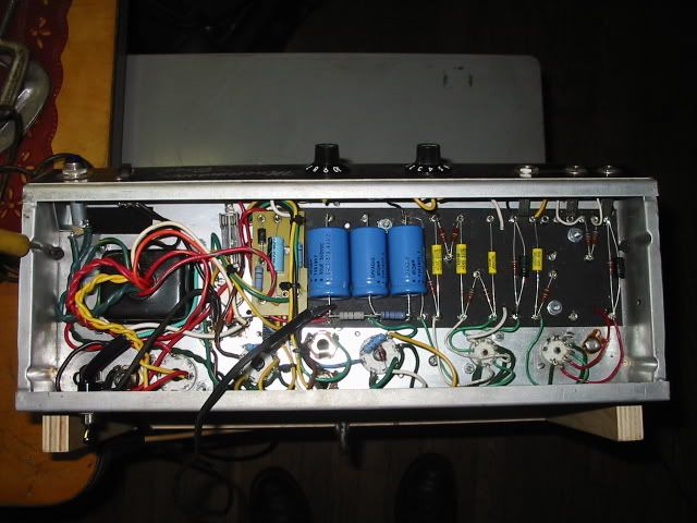
 This is the same chassis before I made the changes . Compared to the way it started out and even though I tried to re-route leads to make it look cleaner and neater it looks like more of a mess than before. I wanted to turn the OT around so the secondary leads were not inside the amp and across the filter cap yet there is no other place to route them so they would clear the eyelet board and not end up to close to the output tubes . I couldn't find a better spot for the B+ fuse . This is what happenes when you keep changing things .

 I moved the bias board off the eyelet board and added on more filter cap and dropper . I also had a standoff where the AC line leads connected so I removed the standoff and spliced the leads so they were not in the way . I read somewhere that the white lead on most amps should be tucked in a corner but I had no corner to tuck it in. I suppose this has something to do with noise. This was stated on some amp kit I got years ago. I also moved the B+ fuse to the side .  I also changed the BF 80's faceplate back to the 77 SF because I had the NFB switch where the extra input jack was , I just put the jack in there to cover the hole I should have never have drilled. When I had the NFB switch there I had a lot of noise that's why I moved the switch to the rear plus I wanted the amp like it looked original with the old SF faceplate and now there is no hole to cover. The SF plate was still in great shape just a few tiny marks near the input jacks .

 This is the rear of the chassis showing where the switch is on the right . on the left that is the standby switch but I leave it on .
« Last Edit: March 13, 2013, 05:54:13 pm by catnine »


Choose a link from the
Hoffman Amplifiers parts catalog
Mobile Device
Catalog Link
Yard Sale
Discontinued
Misc. Hardware
What's New Board Building
 Parts
Amp trim
Handles
Lamps
Diodes
Hoffman Turret
 Boards
Channel
Switching
Resistors Fender Eyelet
 Boards
Screws/Nuts
Washers
Jacks/Plugs
Connectors
Misc Eyelet
Boards
Tools
Capacitors Custom Boards
Tubes
Valves
Pots
Knobs
Fuses/Cords Chassis
Tube
Sockets
Switches Wire
Cable


Handy Links
Tube Amp Library
Tube Amp
Schematics library
Design a custom Eyelet or
Turret Board
DIY Layout Creator
File analyzer program
DIY Layout Creator
File library
Transformer Wiring
Diagrams
Hoffmanamps
Facebook page
Hoffman Amplifiers
Discount Program