Welcome To the Hoffman Amplifiers Forum

September 06, 2025, 12:06:52 am
guest image
Welcome, Guest. Please login or register.
-User Name
-Password


Hoffman Amps Forum image Author Topic: PCMIA parallel port interface  (Read 11402 times)

0 Members and 1 Guest are viewing this topic.

Offline EL34

  • Administrator
  • Level 5
  • **********
  • Posts: 10407
  • wooot!
    • Hoffman Amplifiers
Hoffman Amps Forum image
PCMIA parallel port interface
« on: October 03, 2013, 08:03:15 am »
Calling all solid state guys, refer to my diagram

I have a simple 2N7000  FET/relay circuit that I have used on my CNC desktop PC to turn things on and off
Mach3 can send a M3,M4, M7 or M8 and an output pin will go high or low

It works great a desktop computer with a parallel port
The output pins go high at 5 volts dc and low to zero on that computer and this is enough to trigger the gate on the FET

Ok, so now I want to use the same circuit on my 3D printer except that I am running a notebook computer with a PCMIA slide in parallel port card
The card works great so far controlling Mach3's stepper motors, but I am having an issue with the output pin voltages and my relay circuit

Instead of a steady +5 volts DC when an output pin goes high, I get a voltage that jumps all over the place
I can't get a solid reading but it looks as though it goes from +2.5 volts back down and up, down, up, etc

This wavering voltage is not enough to trigger the FET gate
I can touch my finger to the gate pin and the FET will trigger and the relay coil engages
Someone on the CNC zone forum suggested I use a NPN transistor in front of the FET gate to assist

The available output pins on the parallel port are 1, 14, 16 and 17
All the other output pins are being used by the Stepper motor driver boards 2,3,4,5,6,7,8,9

I am thinking it is some sort of power saving deal that laptops and notebooks use
Anyone have any dealings with PCMIA parallel port cards and why I can't get a steady output voltage on the pins?

Any mods to the circuit shown below are welcome

Offline sluckey

  • Level 5
  • *******
  • Posts: 5075
    • Sluckey Amps
Hoffman Amps Forum image
Re: PCMIA parallel port interface
« Reply #1 on: October 03, 2013, 08:41:55 am »
Rather than stealing +12V from the computer to power the relay, try using an independent/dedicated +12V supply. Also consider using an optoisolator chip for the switching (gate) signal.

EDIT... Do you have a scope that you can use to check the gate signal?
« Last Edit: October 03, 2013, 08:45:06 am by sluckey »
A schematic, layout, and hi-rez pics are very useful for troubleshooting your amp. Don't wait to be asked. JUST DO IT!

Offline EL34

  • Administrator
  • Level 5
  • **********
  • Posts: 10407
  • wooot!
    • Hoffman Amplifiers
Hoffman Amps Forum image
Re: PCMIA parallel port interface
« Reply #2 on: October 03, 2013, 08:45:16 am »
No, I have a 7 amp external power supply
It has to power all the stepper motors, relay boards, etc

The computer parallel port only provides Hi-Lo signals

I would need assistance for that circuit, I's been so long since I messed with any solid state circuits

Offline PRR

  • Level 5
  • *******
  • Posts: 17082
  • Maine USA
Hoffman Amps Forum image
Re: PCMIA parallel port interface
« Reply #3 on: October 03, 2013, 11:01:37 am »
> PCMIA slide in parallel port card
> Instead of a steady +5 volts DC when an output pin goes high, I get a voltage that jumps all over the place... it looks as though it goes from +2.5 volts back down and up


My hasty thought is: it shouldn't do that.

Which printer-signal pin are you using?


Offline EL34

  • Administrator
  • Level 5
  • **********
  • Posts: 10407
  • wooot!
    • Hoffman Amplifiers
Hoffman Amps Forum image
Re: PCMIA parallel port interface
« Reply #4 on: October 03, 2013, 11:08:40 am »
That's how many CNC machines interface with the computer

The parallel port goes to a breakout board that gives you better access to all the pins

Output pins go to the stepper motor driver boards
4 output pins  are available to control things like spindle motors, charge pumps, coolant pumps, etc

My question in more along the lines of why a PCMIA parallel port card differs so greatly from a desktop port?


Offline sluckey

  • Level 5
  • *******
  • Posts: 5075
    • Sluckey Amps
Hoffman Amps Forum image
Re: PCMIA parallel port interface
« Reply #5 on: October 03, 2013, 11:16:17 am »
Here's a typical optical interface. The advantage is the relay circuit is totally isolated from the computer. You don't even need to connect the two grounds together. However, I don't really think this will be the answer. That jumpy print signal needs to be looked at with a scope. Is the signal really about 2.5V or is your meter just averaging highs and lows. 2.5v is a maybe high, maybe low.

Is the laptop operating on internal battery? If so, run it off AC and see if that makes a diff.

Here's the opto. The 4N33 came to mind, but it may be obsolete by now. It's been around a long time. There are better and simpler optos available now such that you don't even need a limiting resistor. I'd have to research to find a good/cheap number. Ideally, you want a 4 terminal device, capable of isolating a logic level input and directly driving a relay (or other open collector load).
A schematic, layout, and hi-rez pics are very useful for troubleshooting your amp. Don't wait to be asked. JUST DO IT!

Offline EL34

  • Administrator
  • Level 5
  • **********
  • Posts: 10407
  • wooot!
    • Hoffman Amplifiers
Hoffman Amps Forum image
Re: PCMIA parallel port interface
« Reply #6 on: October 03, 2013, 11:42:22 am »
yeah, the notebook is running on AC

notebooks and laptops have power miser functions built into them and that may be what's going on

hard to tell with my digital meter what the level is

I hooked it up to the CNC computer which is a desk top box and I get a rock steady +5vdc on the output pins

Funny thing on the notebook is that the stepper motor driver boards use output pins also and the motors all work perfectly fine
But the drivers all have solid state chips on them and so it looks as though they are having no trouble dealing with the output levels

Maybe I will give the NPN transistor idea whorl and see if it works
This is what a guy on CNC zone was suggesting

Quote
Try this. The mosfet looks like it needs more drive voltage.
Use a common base NPN transistor circuit.
10k and 2.7k voltage divider
Base of NPN transistor junction to center of voltage divider resistors

 top resistor goes to 12v.
 bottom resistor goes to 0v.
 That will give 2.55v on the base.
 Connect port output to the emitter.
 Connect the collector to the gate of mosfet, with a 10K pullup.
 You might need to make the 2.5 higher or lower by changing value of one of the base resistors.
« Last Edit: October 03, 2013, 12:15:31 pm by EL34 »

Offline LHPcope

  • Level 1
  • *
  • Posts: 50
    • DCCable
Hoffman Amps Forum image
Re: PCMIA parallel port interface
« Reply #7 on: October 03, 2013, 12:10:06 pm »
From personal experience, laptop power supplies are really P.O.S. It amazes me they manage to allow their respective laptops to operate.  You will find the DC jumps around depending on what is getting used in the laptop (CPU, RAM, harddrive, etc.), and since they are switch mode supplies the voltage doesn't just sag.  Get your commands out of the laptop on some communications protocol and deal with it in a separate box with its own power supply.    
« Last Edit: October 03, 2013, 12:28:49 pm by LHPcope »

Offline sluckey

  • Level 5
  • *******
  • Posts: 5075
    • Sluckey Amps
Hoffman Amps Forum image
Re: PCMIA parallel port interface
« Reply #8 on: October 03, 2013, 12:57:35 pm »
Quote
Get your commands out of the laptop on some communications protocol and deal with it in a separate box with its own power supply.   
That could be a very good solution if your software can talk to RS232 or USB.
A schematic, layout, and hi-rez pics are very useful for troubleshooting your amp. Don't wait to be asked. JUST DO IT!

Offline PRR

  • Level 5
  • *******
  • Posts: 17082
  • Maine USA
Hoffman Amps Forum image
Re: PCMIA parallel port interface
« Reply #9 on: October 03, 2013, 01:01:13 pm »
I'm still wondering which "printer port" pins are involved. They have different timings and handshakes. This PCcard may be playing loose with assumptions.

The classic Centronics interface was TTL. That means the input is two diode-drops and sucks current (fraction mA). The most obvious common-part receivers are TTL with high-current (relay) output, and good-old TIP120 (Darlington, ~~1.2V threshold). With TIP120 I would add 1K-2K from port out to TIP Base. The collector can pass many Amps with heatsink, small-relay loads just naked.

Offline EL34

  • Administrator
  • Level 5
  • **********
  • Posts: 10407
  • wooot!
    • Hoffman Amplifiers
Hoffman Amps Forum image
Re: PCMIA parallel port interface
« Reply #10 on: October 03, 2013, 01:17:24 pm »
I already have access to the pins on my CNC breakout board.
And they do go high and low when I issue a command in Mach3

All that stuff is controlled by Mach3, motors, inputs from limit switches, etc and it all works fine
Mach3 sends Gcode commands and controls the parallel port
Then the motors move, etc

The only issue is the strength of the high-low signal on the port pin I am using for an output
what I am trying to solve is how to get the FET to engage the relay coil

PRR,
The diagram below shows all the pins being used by the motors and the spare outputs which are pins 1, 14, 16 and 17
2,3,4,5,6,7,8,9 are motor control pins

Then there are pins that are used for inputs like limit switches, emergency stop, etc 10,11,12,13,15
All the motor control pins and input pins work just fine


« Last Edit: October 03, 2013, 01:23:32 pm by EL34 »

Offline PRR

  • Level 5
  • *******
  • Posts: 17082
  • Maine USA
Hoffman Amps Forum image
Re: PCMIA parallel port interface
« Reply #11 on: October 03, 2013, 05:47:52 pm »
> voltage that jumps all over the place
> This wavering voltage is not enough to trigger the FET gate


It shouldn't "waver". DMMs can be dumb. Do you have an oscilloscope?

The MOSFET has an uncertain turn-on voltage.

"Genuine" printer ports go up to 3.7V. Working on lower voltages they may not get that high. The original reference was >1.2V, the threshold of TTL.

Sluckey's LED interface has a predictable 2V turn-on. That should/probably work.

A Darlington has predictable 1.3V threshold. That's gotta work.

ULN2803 is an old-old TTL-to-motor/relay chip which really gotta work.

> The available output pins on the parallel port are 1, 14, 16 and 17

It is a *printer* port. Each pin nominally has a specific function.

On the IBM PC, and many-many-many clones, in fact each pin can be addressed and flogged individually, as a general-purpose bit-wise port.

However you are having trouble with a somewhat specialized plug-in card. It *may* only support "printing", not arbitrary bit-setting.

It's been 20 years since I bit-boffed naked printer ports, and 10 years since I handled a PCMIA card, so I need clues to stir what is left of my memory.

Which is why I'd *like* to know if you are using STROBE, LINEFEED, ERROR, or SELECT.

Offline LHPcope

  • Level 1
  • *
  • Posts: 50
    • DCCable
Hoffman Amps Forum image
Re: PCMIA parallel port interface
« Reply #12 on: October 03, 2013, 10:20:07 pm »
The issue is with the Laptop power supply most likely.
 I had a similar problem with a RS232 /USB converter with link monitoring that I was responsible for developing.  The finished piece worked great on a desk top but kept throwing errors on any laptop we tried it on.  I finally had to put a scope on the 5 vdc on the USB port, which is where the converter was getting its power, and monitor that while watching the data and the monitoring errors to confirm the problem with the laptop(s) power supply stability.

Offline EL34

  • Administrator
  • Level 5
  • **********
  • Posts: 10407
  • wooot!
    • Hoffman Amplifiers
Hoffman Amps Forum image
Re: PCMIA parallel port interface
« Reply #13 on: October 04, 2013, 06:27:07 am »
I have the notebook computer dumbed down as much as possible
It's a dual core Pentium Gateway Notebook and it does have some muscle
But it did not have a parallel port so I added the PCMIA card port

It came with Vista but I wiped the drive clean and clean installed XP pro
All eye candy, bells and whistles turned off. Classic windows views, etc
Startup items and Services reduced to bare minimum

Mach3 has it own pulsing engine that controls steppers motors but they warn on the Mach3 forum that laptops and notebooks sometimes have issues because they are built with power saving built into them

Other than that, it is bare bones PC with hardly any software installed
Mach3 and Guitar rig are the two programs I use it for

I checked the bios to see if there were any settings that I could tweak but it's a bare bones bios
The only thing I can think of tweaking now is the Control panel Power Plan settings
I'll go through those and see if some of the hardware like USB, etc is under the control of power savings
I always use it with the AC adapter so power saving is not important

All the hardware below works just fine using the pins that it needs to function

PRR,
I don't address any of the pins manually, Mach3 does all that when it controls the port
The pins that Mach3 uses are shown in my diagram

The printer cable goes to a parallel port breakout board and this is where all the pins are exposed to hookups
Here's a link and shot of that card
http://www.probotix.com/wiki/index.php/PBX-2


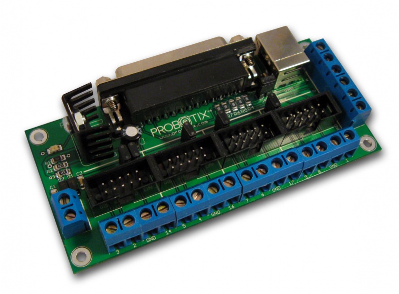
The 4 motor stepper drivers attach to the breakout board above via ribbon cables


Offline LHPcope

  • Level 1
  • *
  • Posts: 50
    • DCCable
Hoffman Amps Forum image
Re: PCMIA parallel port interface
« Reply #14 on: October 04, 2013, 09:23:55 am »
So, you have a command in Mach3 that through the fet/relay turns on the CNC machine in preparation for work commands also from Mach3.  The problem is with the laptop the CNC machine is randomly cutting off during work, correct?  Or some variation of that like when the PCMIA card is initialized on boot up the CNC machine is turned on, right? 

Offline LHPcope

  • Level 1
  • *
  • Posts: 50
    • DCCable
Hoffman Amps Forum image
Re: PCMIA parallel port interface
« Reply #15 on: October 04, 2013, 10:24:39 am »
Assuming that I was correct with my earlier post a peak hold circuit should do the trick.  Adjust the time constant to get in the ball park and fine tune with the pot adjustment.  That should keep the lights on.

Offline EL34

  • Administrator
  • Level 5
  • **********
  • Posts: 10407
  • wooot!
    • Hoffman Amplifiers
Hoffman Amps Forum image
Re: PCMIA parallel port interface
« Reply #16 on: October 04, 2013, 10:36:34 am »
No cutoffs during the entire Gcode program
All that works just fine and the stepper motor driver boards have no problem reading the signal on those output pins

Just to give you an idea how CNC's work

Mach3 reads a Gcode file line by line and processes that into motor movements
Gcode inserted into the program can also turn on spindles, coolant pumps etc
M7 turns on a coolant pump with a relay circuit like I am using
M9 turns off the coolant

There are several others commands like M3, M4, M5, M8, etc

Anywho, I just solved the issue
The guy on CNC zone has it correct
The FET just needed some help
I added a NPN transistor to the FET gate and it works like a charm now
The relay clicks on with M7 and off with M9 in mach3

here's the circuit
« Last Edit: October 04, 2013, 10:39:24 am by EL34 »

Offline LHPcope

  • Level 1
  • *
  • Posts: 50
    • DCCable
Hoffman Amps Forum image
Re: PCMIA parallel port interface
« Reply #17 on: October 04, 2013, 12:12:48 pm »
Good deal!

Offline DummyLoad

  • SMG
  • Level 5
  • *****
  • Posts: 5790
Hoffman Amps Forum image
Re: PCMIA parallel port interface
« Reply #18 on: October 09, 2013, 05:37:44 pm »
couldn't you have used a darlington? e.g. TIP120 or similar...

--pete

Offline EL34

  • Administrator
  • Level 5
  • **********
  • Posts: 10407
  • wooot!
    • Hoffman Amplifiers
Hoffman Amps Forum image
Re: PCMIA parallel port interface
« Reply #19 on: October 09, 2013, 07:43:19 pm »
I don't know what that is  :l2:

I am not familiar with much solid state stuff

The circuit shown above works perfectly so far

Offline DummyLoad

  • SMG
  • Level 5
  • *****
  • Posts: 5790
Hoffman Amps Forum image
Re: PCMIA parallel port interface
« Reply #20 on: October 10, 2013, 04:02:59 pm »
I don't know what that is  :l2:

I am not familiar with much solid state stuff

The circuit shown above works perfectly so far

i don't doubt that it does. sooner or later thought, you're going to want to switch something that the little TO-92 package can't handle. yes, you can use small relay to turn on bigger relay, but, single xsistor driver saves parts count, $$, and chassis real-estate.

a darlington is a very high "gm" transistor - breathe on it  ( not really ;) ) and it turns on. darlingtons can sink/source lots of current with very little drive current. for example a darlington with beta (hFe) of 1000 can switch on/off 1A of DC current with only 1mA of DC base drive current. very handy for switching on motors, solenoids, relays, etc..

another handy device to interface to PC I/O:

Relay interface to microcontroller by ULN 2003

http://www.st.com/st-web-ui/static/active/en/resource/technical/document/datasheet/CD00001244.pdf

mouser stocks both - the darlingtons and the ULN2003 IC.

--pete

Offline EL34

  • Administrator
  • Level 5
  • **********
  • Posts: 10407
  • wooot!
    • Hoffman Amplifiers
Hoffman Amps Forum image
Re: PCMIA parallel port interface
« Reply #21 on: October 11, 2013, 05:50:38 am »
Thanks guys, the circuit I showed above works great so far
If I ever need some other solution I'll refer back to this post

I am switching 12 volts Dc and the load is 3+ amps
the relay is beefy enough for this task
I have used the same relay for switching 24 vdc and 120vac

The 40 watt cartridge heater is being turned off after a print job finishes
The M9 Gcode command in Mach3 controls the parallel port output pin I am using

Here is the relay board I built


Choose a link from the
Hoffman Amplifiers parts catalog
Mobile Device
Catalog Link
Yard Sale
Discontinued
Misc. Hardware
What's New Board Building
 Parts
Amp trim
Handles
Lamps
Diodes
Hoffman Turret
 Boards
Channel
Switching
Resistors Fender Eyelet
 Boards
Screws/Nuts
Washers
Jacks/Plugs
Connectors
Misc Eyelet
Boards
Tools
Capacitors Custom Boards
Tubes
Valves
Pots
Knobs
Fuses/Cords Chassis
Tube
Sockets
Switches Wire
Cable


Handy Links
Tube Amp Library
Tube Amp
Schematics library
Design a custom Eyelet or
Turret Board
DIY Layout Creator
File analyzer program
DIY Layout Creator
File library
Transformer Wiring
Diagrams
Hoffmanamps
Facebook page
Hoffman Amplifiers
Discount Program


password