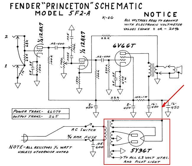
OK, no problem. Conceptually, it is quite the weird thing for newbs to understand that high DC volts in a tube rectifier comes off a filament wire/pin. It's just so...unintuitive. But it does.
You were proposing to place the stby switch (electrically) by cutting one of the yellow filament wires for the 5Y3 rectifier.
My suggestion is not to touch any of the wires in the red box, and to place the stby switch where the red arrow points. Meaning THAT is the wire you cut.

THAT wire, the one I'm suggesting you cut, is physically soldered to one of the rectifier tube pins, either 2 or 8, but is NOT one of the yellow wires that comes out of the tranny.
It appears, from the schematic, that where I am proposing you cut your wire is "a dot in the air" that you probably recognize as an electrical connection, but I assure you, the actual place where that "dot" is, is upon either pin 2 or 8 of your rectifier tube. The OTHER filament pin, nothing is connected there but the single yellow wire from the tranny. Forget that one. You want to cut the non-yellow wire connected to the OTHER filament pin and place your stdby switch in the middle of that wire.
AND BY THE WAY, DO NOT TOUCH ANY OF THESE PARTS until power has been shut off to the amp for a good 5 minutes...even better, MEASURE the DC volts on either pin 2 or 8 of your rect tube relative to ground (chassis) and don't touch anything
until that reading is in single digits.
