Welcome To the Hoffman Amplifiers Forum

September 08, 2025, 03:20:41 am
guest image
Welcome, Guest. Please login or register.
-User Name
-Password


Hoffman Amps Forum image Author Topic: Which other parts can I cut from this schematic ? (old recorder to guitar amp)  (Read 6563 times)

0 Members and 1 Guest are viewing this topic.

Offline kagliostro

  • Level 5
  • *******
  • Posts: 7739
The idea is to convert this old UHER tube recorder in a small guitar amp

here attached you can see the original recorder schematic and the lightened version I've cut

I think is possible also to cut out a part of the Radio Phono intake and may be other parts that I don't understand very much in detail

like the small circuit around the inductor connected to the cathode of V2a

I would like to preserve the EM84 tube, but I'm not sure about the right point of connection as to be used for "VU meter" in the amp

---

One thing I'm not able to understand well is also the connection between the cathode resistor of the EL95 tube and the secondary of the OT (an NFB ?)

instead, seems to me to understand the function of the switch that connects the bypass capacitor and Rk to ground or to the 15k resistor, a sort of mute ? correct ?

---

any council about cuts to be done and mod to the circuit is appreciated

Thanks

K

p.s.: I hope I haven't cut more than due  :think1:

« Last Edit: June 02, 2014, 04:57:52 am by kagliostro »
The world is a nice place if there is health and there are friends

Offline HotBluePlates

  • Global Moderator
  • Level 5
  • ******
  • Posts: 13127
like the small circuit around the inductor connected to the cathode of V2a

I *think* the inductor and many of the connected caps form the "bias oscillator" to to feed an erase signal to the Erase Head, which engages the same time the OT output is grounded at the speaker. But I just glanced at it quickly; maybe PRR recognizes it right away.

Offline printer2

  • Level 2
  • **
  • Posts: 235
Starting from the back, R30 and C20 goes to ground as in switch position A.

R33 might be a little high and may give too much compression, probably should leave it until the rest of the amp is the way you want it.

Hook up R36 as a volume pot to be used as a master.

R27, leave for now but can be used to do some fine tuning.

C12, 0.25uF seems pretty high for a guitar amp especially if you want to overdrive the output tube.

Take out C11.

R19, put a resistor in parallel with it or replace with nothing higher than 1M. Maybe one of the 220k? Get a cathode resistor on this triode. Maybe R31 or R4, 15k.

EF86, no reason to use a grid leak circuit with a guitar, you have lots of signal. Somebody suggest some standard value for a cathode resistor. I have a report to write and I should not be doing this right now. Go in through the mic input, use R3 in place of R7 if it is long enough.

Maybe R9, 47k to replace R30, 120k as the feedback resistor going to the top of R13. The rest of the stuff below the circuit ground on the left of the power supply and above the signal level tube you can remove.


Anybody want to second guess the above as a sanity check?


Offline kagliostro

  • Level 5
  • *******
  • Posts: 7739
Thanks HotBluePlates & Printer2

About the original schematic I can add a little clue that, may be, can be of some help on understanding how it works

The W and A position indicated on some switch, easily mean:

A = Anmeldung = Recording

W = Wiedergabe = Reproduction

Franco
The world is a nice place if there is health and there are friends

Offline HotBluePlates

  • Global Moderator
  • Level 5
  • ******
  • Posts: 13127
First things first: Do you have this actual tape machine, and want to convert it into a guitar amp? Is it working?

Offline PRR

  • Level 5
  • *******
  • Posts: 17082
  • Maine USA
You need two hi-gain triodes between guitar and small power tube.

*NOT* a pentode and two hi-gain triodes!!

It will be a hundred times too sensitive. Impossible to play.

(They used that much gain because tape can be weak; also they rigged V2a V2b inside a NFB loop to set tape record/play equalization; as well as the EL95 NFB. We don't need EQ, and we probably do not want NFB on a small amp.)

So take-out one stage. Try keeping the pentode, plus one triode.

EF86 stage gain is ~~180
ECC83/12AX7 stage gain is ~~25
EL95 stage needs ~~9V peak for full output

So 9V / 25 means 0.36V at ECC83 grid

0.36V / 180 means 2mV at EF86 grid

1mV input for full output is a very high-gain guitar amplifier, usually aimed at heavy-metal work. 2mV is also brutal. You will want to keep the Volume control way down, on amplifier and on guitar. You may want a "master volume" between triode stage and EL95, though if turned-down too much you lose actual Watts output. You may, in the end, decide the EF86 stage is TOO much gain for guitar inputs, in which case I would skip it and wire the ECC83 as a 12AX7 Champ, keeping Uher's values for the EL95 stage.

The magic-eye tube will work connected to the signal at EL95 grid, though it won't go all the way light (dark?). If you do a MV control, tap the eye from before the MV pot. When turned-down the signal will be greater.

Offline kagliostro

  • Level 5
  • *******
  • Posts: 7739
@ HotBluePlates

Quote
First things first: Do you have this actual tape machine, and want to convert it into a guitar amp? Is it working?

OK, as to say it all, all starts with the request of a guy in an italian forum, he asked explanations about some details he didn't understand about a well documented mod, a Geloso G256 (or G257 or G258) tape recorder converted in guitar amp (on which heaters circuit there was something that lighted my curiosity), something that has to do with the Rock in Argentina, see this tread

http://el34world.com/Forum/index.php?topic=17100.msg170616#msg170616

(It is a pity that speech is in Argentinian and you can not understand the explanations and the story of the little Geloso in the Argentine Rock)

and this conversion

http://www.assabbi.com/mods/gelosog258/index.html


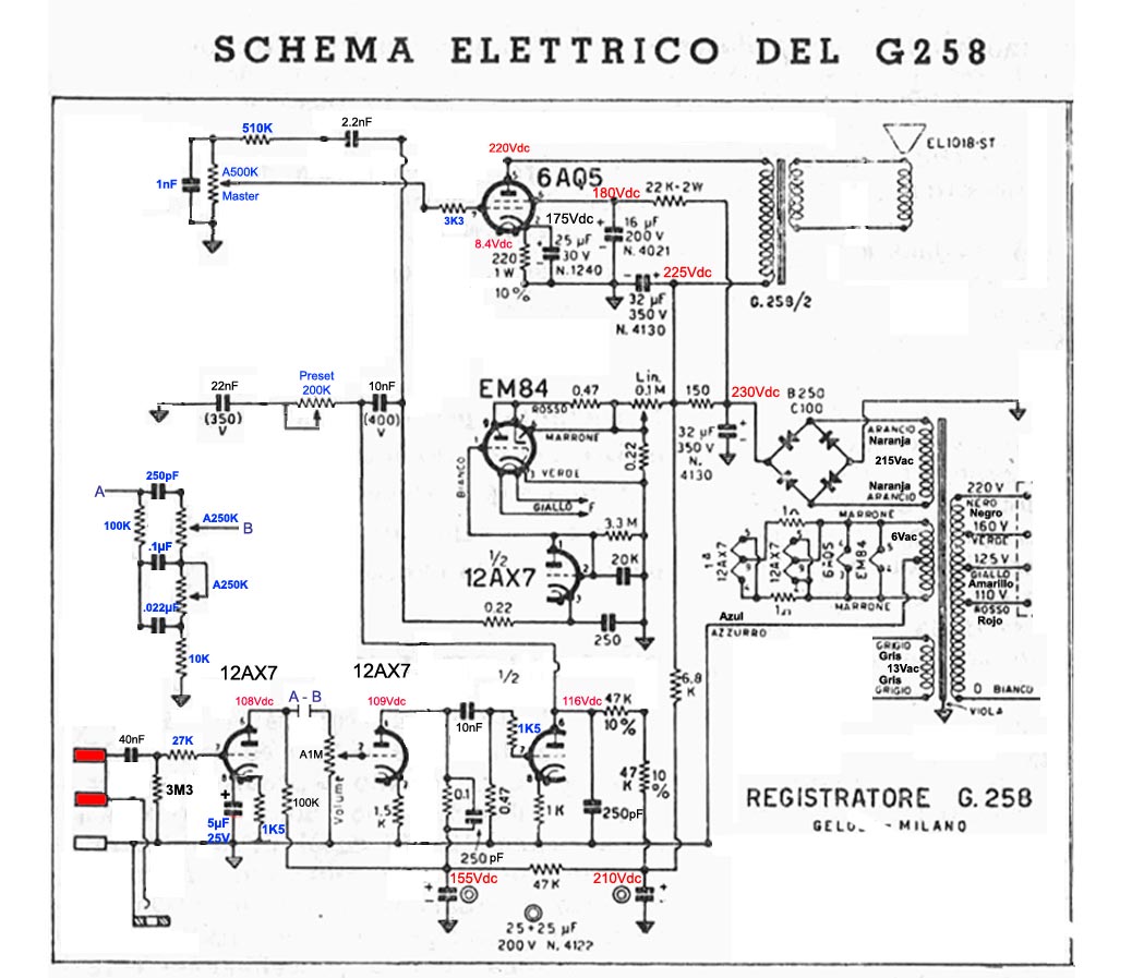
In the past week there where a pair of Ham Flea Markets in Mantova and Bassano del Grappa, and as often, I go there with my Radio Amateur friend (he often has something to barter), I was looking for a Geloso (possibly a G258) but I find that there was an UHER recorder disposable on the cheap (10.00 €, that here is quite near a piece of bread) and got it, a pair of hours later arrived a guy (I think he is 88 yo or a bit more old) with some old stuff, he sold me the wanted G258 for 30.00 € (which is a reasonable price to me)

I don't know if the UHER or the G258 are working, also the cabinets aren't in perfect shape, but this didn't matter for my conversion (I think to realize a new cabinet, something like a lunch box coming from a dismanted HP instrument)

here, knowing where to search, isn't difficult to find those old recorders, the day after, in Bassano del Grappa (I got the recorders in Mantova) there was a guy I know that had one G258 and a pair of Grundig TK14 and he told me he has some other at home

I was tempted to get also a TK14 but I ended purchasing a NOS Inverter (230v single-phase / 230v three-phase) to be used to control speed and direction on a 750W three-phase motor

@ PRR

I like the idea you expose on the schematic (and many thanks for the indication about the intake for the EM84 tube), looking to your schematic and thinking about a possible use for the unused tube (I don't know if this is a good idea, please give me your opinion) in my mind comes the idea to use that triode as a CF as to drive a TS (may be a James or a Merlin's BoneRay)

An alternative, that I'm asking if feasible, will be to use both triodes as they are and tame the gain of both tubes EF86 & 12AX7 using low value plate resistors or to swap the 12AX7 for a ...... tube ?? (I've a lot of 12AU7 and some 12AT7 tubes)

MANY THANKS friends

Franco


« Last Edit: June 03, 2014, 02:19:26 am by kagliostro »
The world is a nice place if there is health and there are friends

Offline kagliostro

  • Level 5
  • *******
  • Posts: 7739
Well, this night I woke up with an idea on my brain


I was thinking to arrange the circuit as to have more switchable channels


One channel will be something like the 5C1 circuit, with only the EF86 and the EL95 tubes in the path

One channel that uses only the 12AX7 tube like in the 5F2 and the EL95 tube

Looking on the web for some inspirations I've find something that looks very interesting to me, this schematic

which incorporates an idea that was going around on my mind some time ago
(the connection of the EF86 tube in a circuit similar to the Vox where there is a TopBoost arrangement as to have an EF86 with a real TS)


looking further I found also this new version 3 of the Vox AC4 from our friend Terminalgs
(I really would like to hear a sample of the modified AC4)


Source: http://www.dougcircuits.com/AC4details.html

and I remembered about this old tread

http://el34world.com/Forum/index.php?topic=16398.msg161688#msg161688

the recorder has a B+ of 285v not very far from the 299v of the modified AC4, so I think that about B+ I'll not have problems

What I would like to know (and my knowledge is too poor) is if the two option of circuit I have exposed can be used with the EL95 circuit section of the Tape Recorder as is or if is requires to mod the circuit around the Power Tube

Thanks

K


« Last Edit: June 05, 2014, 03:22:17 am by kagliostro »
The world is a nice place if there is health and there are friends


Choose a link from the
Hoffman Amplifiers parts catalog
Mobile Device
Catalog Link
Yard Sale
Discontinued
Misc. Hardware
What's New Board Building
 Parts
Amp trim
Handles
Lamps
Diodes
Hoffman Turret
 Boards
Channel
Switching
Resistors Fender Eyelet
 Boards
Screws/Nuts
Washers
Jacks/Plugs
Connectors
Misc Eyelet
Boards
Tools
Capacitors Custom Boards
Tubes
Valves
Pots
Knobs
Fuses/Cords Chassis
Tube
Sockets
Switches Wire
Cable


Handy Links
Tube Amp Library
Tube Amp
Schematics library
Design a custom Eyelet or
Turret Board
DIY Layout Creator
File analyzer program
DIY Layout Creator
File library
Transformer Wiring
Diagrams
Hoffmanamps
Facebook page
Hoffman Amplifiers
Discount Program


password