Welcome To the Hoffman Amplifiers Forum

September 07, 2025, 06:35:06 pm
guest image
Welcome, Guest. Please login or register.
-User Name
-Password


Hoffman Amps Forum image Author Topic: Having some trouble in my tremolo circuit  (Read 4467 times)

0 Members and 1 Guest are viewing this topic.

Offline hesamadman

  • Level 3
  • ***
  • Posts: 732
Hoffman Amps Forum image
Having some trouble in my tremolo circuit
« on: September 17, 2014, 07:28:07 pm »
I just built another 5 W combo this time using the tremolo circuit. I'm having a little bit of trouble with it. It seems to be working fine and the speed changes fine when I adjust the potentiometer but there is a low frequency thumping when I'm not playing any notes the thumping gets louder as I turn up the volume.

I don't know anything about tremolo or how it works so I was hoping somebody could explain it to me a little bit so that I may be able to understand what's going on and troubleshoot it a little bit.

Offline hesamadman

  • Level 3
  • ***
  • Posts: 732
Hoffman Amps Forum image
Re: Having some trouble in my tremolo circuit
« Reply #1 on: September 17, 2014, 08:38:12 pm »

Offline Jack_Hester

  • Level 3
  • ***
  • Posts: 839
  • Greybeard
Hoffman Amps Forum image
Re: Having some trouble in my tremolo circuit
« Reply #2 on: September 18, 2014, 04:38:37 am »
My old GA-40 does the same thing.  I'm content to leave it that way.  But, as yours is a new build, you can modify to fix.  Look at this circuit:
 
http://el34world.com/charts/Schematics/files/ampeg/Ampeg_B12X.pdf
 
or any of the Ampeg B-12-X models, and see the RC circuit that has a group of .02uf caps and 120K resistors.  I'm told that this will dampen or eliminate your thumping.  Several of the more knowledgeble members here can elaborate on how it functions.  Mine is very quiet, until you input a signal. 
 
Jack
"We sleep safe in our beds
because rough men stand ready in the night
to visit violence on those who would do us harm."

                                                   ---George Orwell

Offline hesamadman

  • Level 3
  • ***
  • Posts: 732
Hoffman Amps Forum image
Re: Having some trouble in my tremolo circuit
« Reply #3 on: September 18, 2014, 06:17:50 am »
Since I am very inexperienced with tremolo, im curious if the fact that I altered the original circuit so much has anything to do with it. I pretty muched changed all the values in the preamp. The thumping is a very undesirable thumping that is overbearing when the volume is set pretty high.

The tremolo is offset on the schematic away from all other parts. So grounding wise, im a little confused as to where to place all grounding.
Could wire routing be an issue. Signal wires too close?
« Last Edit: September 18, 2014, 07:10:51 am by hesamadman »

Offline terminalgs

  • Level 3
  • ***
  • Posts: 700
Hoffman Amps Forum image
Re: Having some trouble in my tremolo circuit
« Reply #4 on: September 18, 2014, 08:05:19 am »
the trem sine wave comes in on V1a's (V1a = pins 1,2,3) cathode resistor and by-pass cap, in fact, they are shared cathode components for V2b.   They are important players, are they still 1.5K and 35/50?  did you change V1a's plate 270K resistor?

Offline sluckey

  • Level 5
  • *******
  • Posts: 5075
    • Sluckey Amps
Hoffman Amps Forum image
Re: Having some trouble in my tremolo circuit
« Reply #5 on: September 18, 2014, 10:35:46 am »
Read this for a good understanding of how the Tremolo phase shift oscillator works...

     http://www.valvewizard.co.uk/trem1.html

In your particular circuit, V2B is the oscillator. Call it LFO for short. The LFO produces a sine wave signal that is applied to cathode follower V2A. That signal is present on the cathode of V2A and is sent to the cathode of the input preamp stage V1A. That signal will wiggle the bias voltage of V1A which will vary the gain of V1A, causing the amplitude of the guitar signal to vary. This is the tremolo effect. It's also called amplitude modulation.

This particular tremolo scheme is very sensitive to lead dress and prone to thumping because it works with such a small guitar signal. All kind of problems may arise due to wire routing, component placement, etc. Just ask anyone that has built a Marshall 1974 18 watt amp.

If you can't eliminate the thumping by varying your layout, you can try putting a resistor (10K to 100K) between V1 pin 3 and V2 pin 3. Remove the wire that connects those pins. I don't know if this will help, but it's what I would try.
A schematic, layout, and hi-rez pics are very useful for troubleshooting your amp. Don't wait to be asked. JUST DO IT!

Offline HotBluePlates

  • Global Moderator
  • Level 5
  • ******
  • Posts: 13127
Hoffman Amps Forum image
Re: Having some trouble in my tremolo circuit
« Reply #6 on: September 18, 2014, 03:21:51 pm »
From a PM:
... I noticed that this is a different style of tremolo than I have seen on Valve Wizard website. It takes up both halves of a triode and my understanding on ones ive seen is they do one. ...

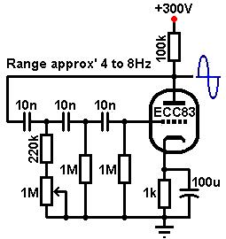
I have since put most values back per schematic. Even if this is a simple fix im curious if I should try the tremolo circuit shown below? It uses less components and seems less complicated? Just for the sake of fitting it in my chassis better than the original.


Jack, Terminalgs and Sluckey already gave you the answer, but I'll summarize them again I one post.

If you carefully draw the Valve Wizard trem and your own trem on a sheet of paper, you'll see they are identical circuits, except some minor parts value changes which will slow down your trem (probably a good thing). Plus you have that 2nd triode.

The 2nd triode has its cathode connected to the cathode of the 1st gain stage; this is the method and location of the trem being injected to effect the guitar signal. The upside of this method is it's easy and checp to incorporate. The downside is that strong trem depth will always cause background pulsing or pumping. It's normal and only avoidable by turning down the trem depth.

If you look again at the trem circuit you provided from Valve Wizard, it's just the oscillator, showing a plate output connected to nothing. In other words, it's not showing how that oscillator signal is couple to the guitar signal, and isn't usable by itself. You would still need a place and a method to inject the trem.

For grounding: on paper, the Gretsch's trem circuit is way away from the preamp, but that's just drawing for clarity/readability. If you follow the plates of the trem circuit back to the filter cap feeding them, you will find it's the 10uF cap furthest from the rectifier. This is also the same filter cap feeding the 1st preamp tube. The 1st preamp tube, trem tube and that last filter cap should all have their grounds directly connected together.

As for the noise: it's unavoidable in this amp circuit, and with this trem injection method. That's why this is an inexpensive student amp (among other reasons, like low power, few features, likely original small speaker, etc). To cancel out most of the trem noise, you'd need to switch to push-pull output tubes and inject the trem at the phase inverter (as in Fender's patented tremolo circuit from the 5E9 Tremolux), or by modulating the bias supply as in later Fender amps like the blackface Princeton. Those inject a common-mode trem signal into a push-pull circuit, so that the trem effects the signal, but the common-mode background noise is rejected.

The downside to the above is you're making a louder amp to start with, and yet you might find you're limited to 6V6's (with very deep trem) or 6L6's (but probably a weaker trem depth).

All this said, if you have a noise that sounds like a distinct "Put-Put-Put-Put" without being a pulsating background noise sound (or the difference between a ramp waveform vs. sine wave), then you probably have poor ground connections especially in the power supply and filter caps (though insufficient power supply dropping resistor size could also cause it). I'm describing motorboating, which you could diagnose by pulling the trem tube from the socket. If the Put-Put-Put is still there, it can't possibly be due to your trem, and is low frequency oscillation through the power supply.

Offline hesamadman

  • Level 3
  • ***
  • Posts: 732
Hoffman Amps Forum image
Re: Having some trouble in my tremolo circuit
« Reply #7 on: September 19, 2014, 09:46:17 pm »
Well guys. Im just now getting around to tweaking the tremolo circuit. I read all of your responses and first thing I did was re-did the layout. I just treated it like additional gain stages would be laid out on any other board. All grounding went where you suggested and wire routing was neat. SOUNDS FANTASTIC. I have a very SLIGHT bit of noise. But the amp is slightly noisy being with the chassis wide open and all. And the grounding is terrible in my shop and all plugs on same circuit as my terrible lighting circuit. Any amp ever played in there is noisy ha. But I think once installed in the chassis and plugged in somewhere else, its going to be great. Im very excited to show everyone this rig once i get it back in the enclosure I built. Its a pretty fancy design. I ordered a load of Celestion Ten 30's for some cabinets we're building and I threw one in here. Im really digging the sound i'm getting. Thanks everyone for your help. Sluckey you are always....ALWAYS a huge help and HBP I cant thank you enough for al the attention on this build. I've been on this forum for a year now and everything I know has come from ll you guys on this site. Thanks again guys!

Offline hesamadman

  • Level 3
  • ***
  • Posts: 732
Hoffman Amps Forum image
Re: Having some trouble in my tremolo circuit
« Reply #8 on: September 22, 2014, 11:25:20 am »
Heres my layout on my board. Sorry if its hard to read. Im still in a cast and hard to write. But basically what Im showing is how im laying out tremolo on my new board and what you think. It filled up a full board. I basically added tremolo circuit on layout between power supply and first preamp tube. The layout goes as follows:


http://rdkelectricalservice.com/amps/Layout%201.jpeg


Left to Right-
Diodes


Power Supply


Cathode of tremolo tube (678 side)
Components for pin 7 of tremolo
Components off pin 6 (many components in series)
Components for pin 2


And then the rest of layout (first preamp tube....layout that HBP gave me a long time ago)


I have a few things ran under the board to connect some components.


Im going to study this and trace it back a few times before I drill and install my turrets.


« Last Edit: September 22, 2014, 11:28:08 am by hesamadman »


Choose a link from the
Hoffman Amplifiers parts catalog
Mobile Device
Catalog Link
Yard Sale
Discontinued
Misc. Hardware
What's New Board Building
 Parts
Amp trim
Handles
Lamps
Diodes
Hoffman Turret
 Boards
Channel
Switching
Resistors Fender Eyelet
 Boards
Screws/Nuts
Washers
Jacks/Plugs
Connectors
Misc Eyelet
Boards
Tools
Capacitors Custom Boards
Tubes
Valves
Pots
Knobs
Fuses/Cords Chassis
Tube
Sockets
Switches Wire
Cable


Handy Links
Tube Amp Library
Tube Amp
Schematics library
Design a custom Eyelet or
Turret Board
DIY Layout Creator
File analyzer program
DIY Layout Creator
File library
Transformer Wiring
Diagrams
Hoffmanamps
Facebook page
Hoffman Amplifiers
Discount Program