Zarrir,
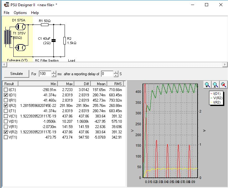
PSUD2 will allow you to estimate what continuous peak diode current occurs in your power supply. Below is an example screen - that simulation model needs to be adjusted with the actual tube model (or something close), and the transformer effective winding resistance, and the max loading, and the capacitors you would use.
It can also identify the turn-on surge peak current - that spec is not in your datasheet but possibly could be the fault current rating (not sure - more background reading is needed).
The rms current levels in the diodes, or resistor, can be used to select a fuse for HT winding protection.
A safer circuit could possibly be to use the 2.5V heater to power the delay relay, but the relay coil voltage would then be non-standard and the insulation rating may not allow that.
A MOV across the HT primary may be a better way to alleviate relay contact arcing.
All the transformers and fuse ratings would need to be cross-checked with the final build, as no current levels or load levels or part numbers are indicated on the schematic.
The mains AC caps are a worry - as you may not have the correct parts.
You may want to test the HT secondary windings for a good damped snubber using a bell-ringer test.
You may want to initially test using ss diodes, to confirm all the circuitry works before finally powering up with the mercury diodes.
These are just a few issues to consider.

