Welcome To the Hoffman Amplifiers Forum

September 06, 2025, 09:51:02 am
guest image
Welcome, Guest. Please login or register.
-User Name
-Password


Hoffman Amps Forum image Author Topic: Matchless Clubman build  (Read 2199 times)

0 Members and 1 Guest are viewing this topic.

Offline didierleclair

  • Level 1
  • *
  • Posts: 6
  • I love Tube amps
Hoffman Amps Forum image
Matchless Clubman build
« on: February 10, 2025, 08:59:41 am »
Hello

I'm building a Matchless Clubman based on this schematic:
https://el34world.com/Forum/index.php?action=dlattach;topic=5730.0;attach=68259;image

I'm using a power transformer with 435Vct secondary from a Conquest Tube65 amp (3x 12ax7, 2x EL34).

I don't really know how the original Conquest amp was designed, but I'm having trouble using this transformer without exceeding the EL34 max. screen voltage. 435V x 1.4 = 609V.
I found some pictures of the inside of the amp but cannot figure it out due to the PTP wiring: https://www.igoramp.it/product/conquest-t65r/

Therefore I am wondering if i could use a 2x 100uF series reservoir cap and tap the screen supply off the half voltage node along with the preamp tube voltages. See attached drawing.

Also, in the Clubman schematic the V1 plate voltage is created using a 220k dropping resistor in the power supply and 18k plate resistor. I have never seen this setup before and don't really know how it works. I'd rather use the Chieftain setup with a 22k dropping resistor and 100k plate resistor.

Any thoughts or feedback?
« Last Edit: February 10, 2025, 01:30:45 pm by didierleclair »

Offline didierleclair

  • Level 1
  • *
  • Posts: 6
  • I love Tube amps
Hoffman Amps Forum image
Re: Matchless Clubman build
« Reply #1 on: February 20, 2025, 10:09:13 am »
well... first results are in.

After much reading i figured it was ok to continue with the split rail power supply design.
Unfortunately i had to give up on the Conquest output transformer because it was shorted.
I installed a tube-town dual primary output transformer, using the 6k6 connections: https://www.tubetown.net/ttstore/en/tube-town-outputtransformer-dual-primary-for-marshall-jtm45.html

Power supply node voltages are:
A 590V (B+)
B 295V (Screens)
C 285V (PI)
D 285V (ef86)
E 135V (V1)

I kept the 220k dropping resistor and 18k plate resistor configuration on V1 for now.
I'll probably play around with the preamp voltages later, but for now it sounds pretty good.

Bias on idle:
Plate voltage for EL34s is 590V
Screen voltage is 295V
Cathode resistors are 470R with 20.7 V across

Plate-to-Cathode Voltage is 590V - 20.7V = 569.4V
cathode current is 20.7V / 470R = 44mA
Anode current is 44mA - 44mA*0.065 = 41.14mA
so plate dissipation per tube is 41.14mA * 569.4V = 23.43W or 93.72%

Not exactly Matchless territory on the plate dissipation % but i'm not really comfortable with anything higher than 100% idle, so the 470R's will probably stay.

Offline AlNewman

  • Level 3
  • ***
  • Posts: 852
  • I love Tube amps
Hoffman Amps Forum image
Re: Matchless Clubman build
« Reply #2 on: February 20, 2025, 05:26:23 pm »
I may be wrong, but I would think you would want your CT referenced to ground.  It might be ok to run your screens off of the balance resistor, but you could even be getting false readings for plate dissipation based on your ground reference.

You could confirm by measuring current across your OT primary windings.

If you had a defective OT before changing the PS wiring, perhaps now with a good OT your voltages would be closer to stock with the original wiring.

Offline didierleclair

  • Level 1
  • *
  • Posts: 6
  • I love Tube amps
Hoffman Amps Forum image
Re: Matchless Clubman build
« Reply #3 on: February 21, 2025, 05:43:58 am »
I may be wrong, but I would think you would want your CT referenced to ground.  It might be ok to run your screens off of the balance resistor, but you could even be getting false readings for plate dissipation based on your ground reference.

In my research i found this reference design. CT reference point is between the stacked reservoir caps.
http://schematicheaven.net/fenderamps/twin_reverb_sf_135_schem.pdf

I think if you reference the CT to ground, the ground reference of the rest of the design would also have to move to the intersection of the stacked reservoir caps to prevent shorting a PT secondary winding. But that would result in a dual rail power supply with +300V and -300V nodes.
These are the options:


Option D is the only setup that gives me the high voltage node and an acceptable screen supply voltage for EL34's.
I essentialy created the screen supply attached, but with the added balancing resistors.
I don't think these resistors pose a problem as they are also incoporated in the fender design above as 2x 100k 1W.

I also found this page (section 5 - Power supplies) an interesting read regarding all this: https://sound-au.com/valves/design2.html#s5

You could confirm by measuring current across your OT primary windings.

I will check bias with this method, i assume you are referring to this?
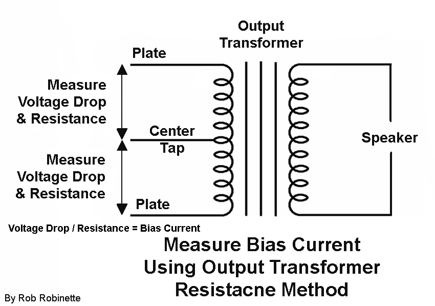

If you had a defective OT before changing the PS wiring, perhaps now with a good OT your voltages would be closer to stock with the original wiring.

No i did not, to be clear this is a new scratch build. I planned to use the available Conquest transformers i had lying around. The OT must have failed while in the Conquest and had not been tested during planning of this build. testing during build revealed it had a shorted winding to the core (and chassis) so i never used it.


In order to further experiment with the preamp voltages i might:
1. move the dropping resistors to the A node.
2. choose higher value dropping resistors for node C & D to drop the 590V to acceptable voltages for 12ax7 and EF86 tubes
3. maybe leave the 220k dropping resistor for node E as is for now and see where the voltage for V1 ends up

for 2. i would like to approach the voltages of the matchless design (+/- 415V), so i would need to drop 175V
with 2mA in the PI 12ax7 that would give me 175V / 2mA = 87k5 (82k?  and dissipating 175V * 2mA = 0.35W
I think the ef86 has a max plate current of 6mA so: 175V / 6mA = 29k (27k?) and dissipating 175V * 6mA = 1.05W
these are not exactly standard values, any thoughts?

Offline pdf64

  • Level 4
  • *****
  • Posts: 2965
Hoffman Amps Forum image
Re: Matchless Clubman build
« Reply #4 on: February 21, 2025, 10:22:40 am »
As far as I can tell, everything you've done looks ok, should work.
I think you'll need to select the OT carefully though, a regular EL34 spec (3k4) may have much too low primary impedance, and the valves will get too hot.

These tools may be helpful with that
http://bmamps.com/ivds.html
https://www.vtadiy.com/loadline-calculators/loadline-calculator/

Bear in mind that your power supply loaded voltages will be lower than when unloaded.
« Last Edit: February 21, 2025, 10:28:18 am by pdf64 »
https://www.justgiving.com/page/5-in-5-for-charlie This is my step son and his family. He is running 5 marathons in 5 days to support the research into STXBP1, the genetic condition my grandson Charlie has. Please consider supporting him! BBC News feature  https://www.bbc.co.uk/news/articles/cm26llp

Offline danhei

  • Level 1
  • *
  • Posts: 90
  • I love tube amps
Hoffman Amps Forum image
Re: Matchless Clubman build
« Reply #5 on: February 21, 2025, 06:09:25 pm »
Also, in the Clubman schematic the V1 plate voltage is created using a 220k dropping resistor in the power supply and 18k plate resistor. I have never seen this setup before and don't really know how it works. I'd rather use the Chieftain setup with a 22k dropping resistor and 100k plate resistor.


Unusually, the Clubman does not have a volume control after the first stage. I’ve never played one but I suspect configuration of the input triode with a very low plate resistor is to drive the tone stack but prevent overdriving the EF86 during most conditions. If you reconfigure the input to a “standard” gain stage you’ll need to add a volume control before the EF86 and figure out how that will interact with the tone controls.

Offline AlNewman

  • Level 3
  • ***
  • Posts: 852
  • I love Tube amps
Hoffman Amps Forum image
Re: Matchless Clubman build
« Reply #6 on: February 22, 2025, 12:00:21 am »
Yes, I would double check across the OT primary using the link you posted.  Since you're elevating the center tap and the cathode is still referenced to ground, the ohms law measurements (could?) get squirrely.

Maybe not though, it will be interesting to see the results.

Offline didierleclair

  • Level 1
  • *
  • Posts: 6
  • I love Tube amps
Hoffman Amps Forum image
Re: Matchless Clubman build
« Reply #7 on: February 22, 2025, 01:12:14 pm »
As far as I can tell, everything you've done looks ok, should work.
I think you'll need to select the OT carefully though, a regular EL34 spec (3k4) may have much too low primary impedance, and the valves will get too hot.

Thank you.
The OT i have now has a dual primary with 8k and 6k6 options. so should be fine.

These tools may be helpful with that
http://bmamps.com/ivds.html
https://www.vtadiy.com/loadline-calculators/loadline-calculator/

I used the vtadiy loadline calculator, the results are attached. I really don't know how to interpret these so I have some more reading to do...

Offline pdf64

  • Level 4
  • *****
  • Posts: 2965
Hoffman Amps Forum image
Re: Matchless Clubman build
« Reply #8 on: February 22, 2025, 03:01:01 pm »
Is that loadline 8k or 6k6?
It's somewhat above the 25W dissipation curve.
Click on the Vg1=0 curve where it crosses the loadline.
https://www.justgiving.com/page/5-in-5-for-charlie This is my step son and his family. He is running 5 marathons in 5 days to support the research into STXBP1, the genetic condition my grandson Charlie has. Please consider supporting him! BBC News feature  https://www.bbc.co.uk/news/articles/cm26llp

Offline didierleclair

  • Level 1
  • *
  • Posts: 6
  • I love Tube amps
Hoffman Amps Forum image
Re: Matchless Clubman build
« Reply #9 on: February 22, 2025, 03:49:51 pm »
Is that loadline 8k or 6k6?

That is 6k6.

Am I supposed to keep the loadline under the max dissipation curve?

What are the options?
Cooling bias?
Dropping B+?
Switching the OT to the 8k primary? Or would I even go higher? Eg. Connecting a 8ohm load to the 4ohm tap while using the 6k6 primary.

Does cathode bias vs. Fixed bias affect how to interpret the load lines? Since we bias near 100% with cathode bias?

Offline didierleclair

  • Level 1
  • *
  • Posts: 6
  • I love Tube amps
Hoffman Amps Forum image
Re: Matchless Clubman build
« Reply #10 on: February 24, 2025, 04:25:22 pm »
Yes, I would double check across the OT primary using the link you posted.  Since you're elevating the center tap and the cathode is still referenced to ground, the ohms law measurements (could?) get squirrely.

Maybe not though, it will be interesting to see the results.

So i've measured across the OT primary, here are the results:

R1 = 68.5R and V1 = 2.68V so that makes I1 = 40.12mA
R2 = 69.2R and V2 = 2.65V so that makes I2 = 38.86mA
with 580V on the plates and 20.1V on the cathode that gives me 90% plate dissipation per tube on idle.

this even makes me wonder if i could lower the cathode resistors from 470R to 390R or 330R...

while measuring I also took note of the preamp plate voltages:
V1 131V
V2 ef86 85V
V3 pi 209V
These are all low so i will continue to experiment with dropping resistor values and maybe move the connection over to node A.

Offline pdf64

  • Level 4
  • *****
  • Posts: 2965
Hoffman Amps Forum image
Re: Matchless Clubman build
« Reply #11 on: February 24, 2025, 06:25:19 pm »
Cathode bias makes a difference, but probably still it's beneficial to avoid idling over 25W anode dissipation here.
It's fine to tweak droppers to achieve the desired supply voltages.
https://www.justgiving.com/page/5-in-5-for-charlie This is my step son and his family. He is running 5 marathons in 5 days to support the research into STXBP1, the genetic condition my grandson Charlie has. Please consider supporting him! BBC News feature  https://www.bbc.co.uk/news/articles/cm26llp


Choose a link from the
Hoffman Amplifiers parts catalog
Mobile Device
Catalog Link
Yard Sale
Discontinued
Misc. Hardware
What's New Board Building
 Parts
Amp trim
Handles
Lamps
Diodes
Hoffman Turret
 Boards
Channel
Switching
Resistors Fender Eyelet
 Boards
Screws/Nuts
Washers
Jacks/Plugs
Connectors
Misc Eyelet
Boards
Tools
Capacitors Custom Boards
Tubes
Valves
Pots
Knobs
Fuses/Cords Chassis
Tube
Sockets
Switches Wire
Cable


Handy Links
Tube Amp Library
Tube Amp
Schematics library
Design a custom Eyelet or
Turret Board
DIY Layout Creator
File analyzer program
DIY Layout Creator
File library
Transformer Wiring
Diagrams
Hoffmanamps
Facebook page
Hoffman Amplifiers
Discount Program