Welcome To the Hoffman Amplifiers Forum

September 06, 2025, 12:12:28 am
guest image
Welcome, Guest. Please login or register.
-User Name
-Password


Hoffman Amps Forum image Author Topic: Relay circuit on my 2204 build  (Read 6847 times)

0 Members and 1 Guest are viewing this topic.

Offline MVDW

  • Level 1
  • *
  • Posts: 4
Hoffman Amps Forum image
Relay circuit on my 2204 build
« on: February 01, 2011, 08:35:24 am »
Hello guys. I'm new here, I'm a guy from the Netherlands and I've just 'finished' my first build, a 2204, except for the relay circuit switching.

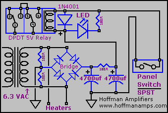
I'm using Doug's circuit from the relay switching page on this site. This one:

Here is my 2204 build that I built using a chassis and trannies of a 2205. It was wrecked so I took the guts out and made myself a hotrodded 4 gainstager with a (supposedly) toggle and footswitch switchable boost triode V0.

Here is a pic of the amp, it wasn't fully finished here but it serves the purpose.


I just can't get the relay circuit to work. I've tried with the transformer center tap to ground, and the ground of the rectifier bridge to ground as well. Didn't work. Then I disconnected only the transformer CT, also didn't work. Then I put the transformer CT back to ground and disconnected the ground side of the rectifier bridge, also no dice obviously as Im rectifying only half.

Will using an artificial CT with two 100 resistors give me more supply voltage than with a transformer CT?

Also, I have another question regarding this. I was also thinking about elevating my heaters to 50 VDC, by using a voltage divider off B+. If I have my transformer CT disconnected I won't be able to reference it to 50 VDC, or can I? But this would mean that I'm rectifying a lot more voltage at the rectifier. The resistor in Doug's schematic between the two 4700uF caps is a 180 ohms one to lower the supply voltage. Can I put a much higher value resistor there instead to lower the voltage to 5 vDC to power the relay circuit?

Thanks!
« Last Edit: February 01, 2011, 08:47:03 am by MVDW »

Offline OldHouseScott

  • Level 3
  • ***
  • Posts: 710
    • Old House Recording Studio
Hoffman Amps Forum image
Re: Relay circuit on my 2204 build
« Reply #1 on: February 01, 2011, 01:55:19 pm »
You should wire it exactly as shown in Doug's diagram. Leave the heater CT disconnected. You should see about 7VDC across the large caps with the switch open. When you close the switch, the LED should light up. Does this much of the circuit work in your build?

If you want to elevate the heaters, it would be best to add a separate transformer to power the relay so you can keep the switching circuit referenced to ground. I wouldn't worry about that though until I got the relay circuit going first.
OldHouseScott
<><

"We put a little quality in everything we build..."

Offline Willabe

  • Global Moderator
  • Level 5
  • ******
  • Posts: 10524
Hoffman Amps Forum image
Re: Relay circuit on my 2204 build
« Reply #2 on: February 02, 2011, 08:38:59 pm »
Hi, MVDW

That is a very good looking build, and it's your first? Looks great.

Hows it sound?


        Brad        :smiley:
 

Offline Tone Junkie

  • Level 3
  • ***
  • Posts: 861
Hoffman Amps Forum image
Re: Relay circuit on my 2204 build
« Reply #3 on: February 02, 2011, 11:38:37 pm »
Very nice looking build clean I like that I wish my frankenstein Im working on now looked even close to that I got to much stuff not enough room(LOL). Bill

Offline MVDW

  • Level 1
  • *
  • Posts: 4
Hoffman Amps Forum image
Re: Relay circuit on my 2204 build
« Reply #4 on: February 03, 2011, 11:29:52 am »
Thanks guys! Yeah, this is my first build.

I must say, the amp can only run on stock 2204 mode now and it sounds really good. Just a bit of noise I'd like to get rid of, but other than that it's pretty sweet. I haven't heard it yet with the added triode, I'll probably have to tweak that though. I added a variable slope resistor as a mid sweep/contour control, a PPIMV, a resonance control, a variable NFB control to change the NFB feedback resistor from around 15k to 265k on the 8 ohm tap and an extra gain control for the added gainstage. Pretty versatile.

More pics when everything is done.
'
Thanks for the advice on the relay circuit. I'll try that when I have some time left one of these days. I used a relay and a LED with the same specs like the one Doug used so it just has to work. I'm not really wanting to use a seperate transformer (although I have one that I took out of the 2205 that was used for the reverb) as it might inconvenient in there. Just a theoretical question though: if I elevate the heaters with let's say maybe 12VDC, will using a slightly larger value limiting resistor work?
« Last Edit: February 03, 2011, 11:51:52 am by MVDW »

Offline MVDW

  • Level 1
  • *
  • Posts: 4
Hoffman Amps Forum image
Re: Relay circuit on my 2204 build
« Reply #5 on: February 05, 2011, 04:43:31 am »
No luck so far guys.

I've wired it with an artificial CT, and I measure around 7,6VDC at the output of the rectifier which is good and SHOULD be enough voltage to power the relay and the LED. The relay and the LED don't work yet.

If the switch is turned off I measure the same 7,6 volts across the relay coil. When I turn the switch on I measure 0 VDC. I thought that if I took the relay out of the IC-socket the LED would still be able to power on. It also doesn't.

I've checked all my wiring, and so far I can't really see a thing wrong with it. Can it be that I swapped my relay coil + and - and the diode? Can't my PT supply enough amps? Or what can be wrong? I'm puzzled.

Offline MVDW

  • Level 1
  • *
  • Posts: 4
Hoffman Amps Forum image
Re: Relay circuit on my 2204 build
« Reply #6 on: February 05, 2011, 12:29:36 pm »
Alright, after going through it several more times and doing measurements everywhere I've managed to fix it.

It's now finally finished and switching works. Turns out I wired the LED the wrong way around, which made me feel stupid. It's a beast now. It has tons of gain and I'm surprised how much it grinds and how tight it is.

I simply love it and the switching is actually very silent. The only thing I'm having right now is when I turn the gain up too high on the added triode I get squeeling and mushy bass, but I can run it to around 7 and it's all fine and has all the gain I'll ever want.

Here are some pics for anyone interested. Thanks for the help on the relay config guys!


Some more:

http://dl.dropbox.com/u/4998086/Marshall%20800%20build/IMG_7384.JPG
http://dl.dropbox.com/u/4998086/Marshall%20800%20build/IMG_7396.JPG
http://dl.dropbox.com/u/4998086/Marshall%20800%20build/IMG_7403.JPG
http://dl.dropbox.com/u/4998086/Marshall%20800%20build/IMG_7405.JPG

Offline alerich

  • Level 3
  • ***
  • Posts: 606
  • This one goes to 11.
Hoffman Amps Forum image
Re: Relay circuit on my 2204 build
« Reply #7 on: February 06, 2011, 03:06:44 pm »
Very nice build and a great idea (never cared for the Marshall channel switchers much). Do you have a copy of the schematic you used?
Some of the most amazing music in history was made with equipment that's not as good as what you own right now.


Choose a link from the
Hoffman Amplifiers parts catalog
Mobile Device
Catalog Link
Yard Sale
Discontinued
Misc. Hardware
What's New Board Building
 Parts
Amp trim
Handles
Lamps
Diodes
Hoffman Turret
 Boards
Channel
Switching
Resistors Fender Eyelet
 Boards
Screws/Nuts
Washers
Jacks/Plugs
Connectors
Misc Eyelet
Boards
Tools
Capacitors Custom Boards
Tubes
Valves
Pots
Knobs
Fuses/Cords Chassis
Tube
Sockets
Switches Wire
Cable


Handy Links
Tube Amp Library
Tube Amp
Schematics library
Design a custom Eyelet or
Turret Board
DIY Layout Creator
File analyzer program
DIY Layout Creator
File library
Transformer Wiring
Diagrams
Hoffmanamps
Facebook page
Hoffman Amplifiers
Discount Program


password