Hello guys. I'm new here, I'm a guy from the Netherlands and I've just 'finished' my first build, a 2204, except for the relay circuit switching.
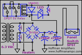
I'm using Doug's circuit from the relay switching page on this site. This one:

Here is my 2204 build that I built using a chassis and trannies of a 2205. It was wrecked so I took the guts out and made myself a hotrodded 4 gainstager with a (supposedly) toggle and footswitch switchable boost triode V0.
Here is a pic of the amp, it wasn't fully finished here but it serves the purpose.

I just can't get the relay circuit to work. I've tried with the transformer center tap to ground, and the ground of the rectifier bridge to ground as well. Didn't work. Then I disconnected only the transformer CT, also didn't work. Then I put the transformer CT back to ground and disconnected the ground side of the rectifier bridge, also no dice obviously as Im rectifying only half.
Will using an artificial CT with two 100 resistors give me more supply voltage than with a transformer CT?
Also, I have another question regarding this. I was also thinking about elevating my heaters to 50 VDC, by using a voltage divider off B+. If I have my transformer CT disconnected I won't be able to reference it to 50 VDC, or can I? But this would mean that I'm rectifying a lot more voltage at the rectifier. The resistor in Doug's schematic between the two 4700uF caps is a 180 ohms one to lower the supply voltage. Can I put a much higher value resistor there instead to lower the voltage to 5 vDC to power the relay circuit?
Thanks!
