Welcome To the Hoffman Amplifiers Forum

September 08, 2025, 09:59:24 am
guest image
Welcome, Guest. Please login or register.
-User Name
-Password


Hoffman Amps Forum image Author Topic: 5F1 Build thread - by a first timer.  (Read 18282 times)

0 Members and 1 Guest are viewing this topic.

Offline Meteorman

  • Level 1
  • *
  • Posts: 55
  • I make all my own mistakes
Hoffman Amps Forum image
5F1 Build thread - by a first timer.
« on: March 01, 2016, 12:35:00 pm »
So I guess I'll document my first build here, not because I think anyone is really interested in seeing another 5F1 build.
I guess these are close to the simplest Tinker Toy one can do for tube amps, and most will find it boring, but....
My incentive is self-preservation, in that hopefully someone can spot my mistakes and point them out before I burn my house down.

Goal is to build the 5F1 with 2 mods: a variable pot in the NFB loop, and a 4/8/16ohm speaker switch.

Still trying to locate some ClassicTone transformers in stock.
I called Triode USA yesterday to see if they were in stock, and I got shunted to a recording that said "Customer Service is not available".
On the whole, that was a somewhat discouraging statement, I thought... 

Anyway, the Hoffman kit arrived very quickly.  Nice service !


I watched a few videos, did some reading, screwed down the board, and did the lacing.


Then spent last night ID'ing and dry fitting the board components.
The resistor color codes didnt seem to match what I was googling up as a guide, but I used my multimeter to correctly ID them all.
Not forgetting the underboard jumper wire.


So if anyone sees anything amiss so far, please yell at me using as many 4-letter words as appropriate.
My intention for the negative feedback circuit is to replace the normal 22K resistor with a 10K resistor on the turrets and run a wire off the 10K to the pot which will be in a to-be-determined spot on the chassis.
Would 18 or 20 gauge wiring be good for that ?
something like this:


I know most of you could build this in your sleep. 
/mike 


« Last Edit: March 01, 2016, 01:26:00 pm by Meteorman »

Offline ratgon

  • Level 2
  • **
  • Posts: 139
  • I love Tube amps
Hoffman Amps Forum image
Re: 5F1 Build thread - by a fi
« Reply #1 on: March 01, 2016, 12:50:32 pm »
The pics all look good but I have no idea what you're trying to say.

Offline sluckey

  • Level 5
  • *******
  • Posts: 5075
    • Sluckey Amps
Hoffman Amps Forum image
Re: 5F1 Build thread - by a first timer.
« Reply #2 on: March 01, 2016, 01:24:33 pm »
Your board looks good. 22AWG is plenty sufficient for the NFB wire. 18AWG is overkill. Looking forward to seeing the entire project so please post more.

Here's a suggestion about that underboard jumper. Put it on top of the board just like all your other jumpers. Or, if you must have it underneath then insert the end of the wire completely thru the top of the turret and bend it over so it cannot possibly fall out when you begin soldering. Here's a pic showing what I mean...


A schematic, layout, and hi-rez pics are very useful for troubleshooting your amp. Don't wait to be asked. JUST DO IT!

Offline SILVERGUN

  • Level 4
  • *****
  • Posts: 3507
Hoffman Amps Forum image
Re: 5F1 Build thread - by a first timer.
« Reply #3 on: March 01, 2016, 01:57:48 pm »
Looking forward to seeing the entire project so please post more.
We really are interested...we were all new builders at one point.
Welcome to Builders Anonymous!
 
Anyway, the Hoffman kit arrived very quickly.  Nice service !
Doug is a consistently fast shipper...tell your friends.
 
One thing I would suggest would be to use good heat sink technique during soldering...you don't want to damage those pretty new caps with all the heat it takes to get them down.
« Last Edit: March 01, 2016, 02:08:32 pm by SILVERGUN »

Offline Shack

  • Level 2
  • **
  • Posts: 308
Hoffman Amps Forum image
Re: 5F1 Build thread - by a first timer.
« Reply #4 on: March 01, 2016, 03:50:00 pm »
As a matter of fact, im grateful you did, because im building a Princeton reverb and didnt run my jumpers as you were instructed, and now I caught it in time thanx to your post :) ...I think it looks good and ill build one later just to have one.
New build problems? Click here.

Offline Shack

  • Level 2
  • **
  • Posts: 308
Hoffman Amps Forum image
Re: 5F1 Build thread - by a first timer.
« Reply #5 on: March 01, 2016, 03:55:26 pm »
can you elaborate on heat sink technique? And yes.....Doug has sent me everything ive ordered within like 4 working days tops , and even personally thanks you .....awesome
New build problems? Click here.

Offline Meteorman

  • Level 1
  • *
  • Posts: 55
  • I make all my own mistakes
Hoffman Amps Forum image
Re: 5F1 Build thread - by a first timer.
« Reply #6 on: March 01, 2016, 07:41:39 pm »
Thanks gents.
I intend to place little alligator clips on the leads between the cap body and the solder point.  Thats the only thing I know to do for heat sinks.  is there something better I oughta consider?

I think I need to sleeve those resistor leads that pass over the lacings, too.

Thanks for the jumper tip, Sluckey. 

/mike

Offline SILVERGUN

  • Level 4
  • *****
  • Posts: 3507
Hoffman Amps Forum image
Re: 5F1 Build thread - by a first timer.
« Reply #7 on: March 01, 2016, 07:53:13 pm »
Thanks gents.
I intend to place little alligator clips on the leads between the cap body and the solder point.  Thats the only thing I know to do for heat sinks.  is there something better I oughta consider?
Nope that's good..
I like to use aluminum clips, so when you have to get close they don't get accidently soldered to the joint.
 
Sometimes I'll use 2 clips, one at the joint and the other up near the cap (or diode) body

Offline Willabe

  • Global Moderator
  • Level 5
  • ******
  • Posts: 10524
Hoffman Amps Forum image
Re: 5F1 Build thread - by a first timer.
« Reply #8 on: March 01, 2016, 08:00:41 pm »
I think I need to sleeve those resistor leads that pass over the lacings, too.

Won't hurt, some guys do. I think it's a good idea.  :icon_biggrin:

Offline Willabe

  • Global Moderator
  • Level 5
  • ******
  • Posts: 10524
Hoffman Amps Forum image
Re: 5F1 Build thread - by a first timer.
« Reply #9 on: March 01, 2016, 08:26:46 pm »
I like to use aluminum clips, so when you have to get close they don't get accidently soldered to the joint.

+1

Offline ratgon

  • Level 2
  • **
  • Posts: 139
  • I love Tube amps
Hoffman Amps Forum image
Re: 5F1 Build thread - by a first timer.
« Reply #10 on: March 01, 2016, 11:14:08 pm »
Honestly I wish everyone was posting progressive updates. They're great! And completely unobtrusive to those that aren't into them. Hmmmm?mit just occurred to me that maybe there's a board in the forum already set up. Beyond that, great work and thanks for taking the time to do this

Offline sluckey

  • Level 5
  • *******
  • Posts: 5075
    • Sluckey Amps
Hoffman Amps Forum image
Re: 5F1 Build thread - by a first timer.
« Reply #11 on: March 02, 2016, 06:44:11 am »
This is the board for posting progress on a build. Many of us love to see pics and hear of progress. Doesn't matter how simple or complex. We like it all!
A schematic, layout, and hi-rez pics are very useful for troubleshooting your amp. Don't wait to be asked. JUST DO IT!

Offline Paul1453

  • Level 3
  • ***
  • Posts: 1085
  • I love Tube amps
Hoffman Amps Forum image
Re: 5F1 Build thread - by a first timer.
« Reply #12 on: March 02, 2016, 04:25:32 pm »
Don't worry, Be Happy!!!

As a 1st time builder you have gone the best way.

You've purchased a proven design/layout, and components from Doug.   :worthy1:
You've started a thread to document your progress, so you now have multiple eyes proofing your work.
You are off to a great start, and your work looks good to me.   :icon_biggrin:

You will be very happy when you finally hear the results of your work.
They always sound better when you built it yourself.   :icon_biggrin:

Offline Meteorman

  • Level 1
  • *
  • Posts: 55
  • I make all my own mistakes
Hoffman Amps Forum image
Re: 5F1 Build thread - by a first timer.
« Reply #13 on: March 03, 2016, 07:35:45 am »
thanks comrades.  so with the bliss of ignorance as my shephard, I made minor progress last night.

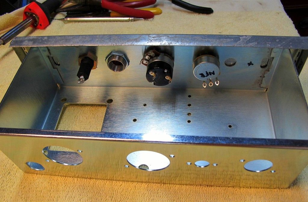
first chore was to modify the chassis control face - I got the chassis off eBay, it's a nice product, but drilled for traditional Champ layout, which I'm going to tweak.
I only want one input jack, and i wanted the NFB pot on the front panel, sort of proxy for a tone pot.
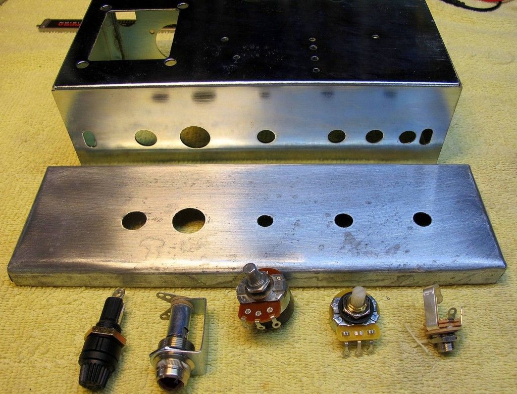
the hole spacing didn't accommodate that config, so I decided to fabricate a faceplate with new hole spacing, then drill the chassis to match that.
Turns out that really only meant one new hole, just moving the input jack hole more towards the edge, and sticking the NFB pot in the (original) 2nd jack hole .
The face plate, which I'll paint and label later, of course then hides the abandoned original 1st input jack hole.
I think I'll spot mig weld the face plate onto the chassis before i put any components aboard.


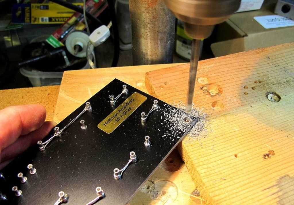
The I did some ciphering on location of the the circuit board - there really isnt a whole lotta wiggle room there as most of you already know  - and drilled the board for its mounting hardware - and transferred those holes locations to the chassis. 
Waitin to drill the chassis until I have transformers in hand & I'm positive I have needed clearance.


So then comes the hard part.  For me anyway.
Doug says, to keep things neat, wire up the chassis infrastructure first, before installing component board (which is 180 degrees from the way I woulda done it, so it has to be right). 
Then install component board and patch it in.

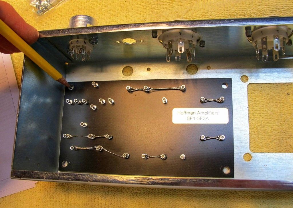
The sharp-eyed will note the 6V6 socket is riveted above but screwed below.  evidence of a mistake.
I needed to swap the orientation of the socket once I saw how the heater wires were going to run.
Drilled out rivets, learned a lesson about thinking ahead.

Started soldering the 12AX7 leads.
Fumbled around soldering with the socket installed in the chassis at first, until it dawned on me that I could just remove the socket and solder it up and then reinstall. Duh.
Confidence was sagging at this point.


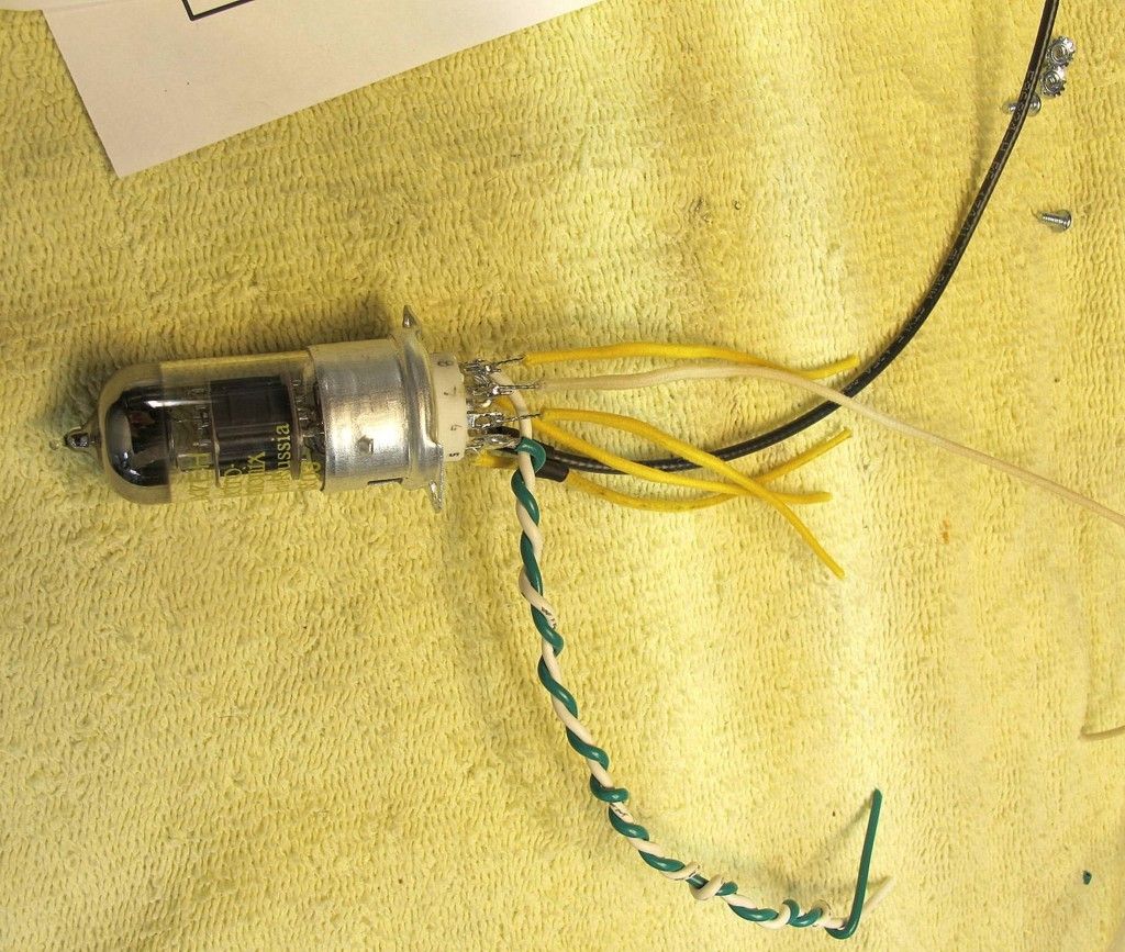
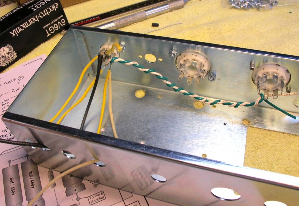
The green white heater wires will go to center 6V6 socket, they just look like they're heading to the rectifier in this pic. ( I'm leaving leads long at first....)
The white and black go underboard to vol pot and input jack, respectively.
Yellows go to board.  The pushback cloth wasn't pushed back prior to these pics - I won't have those bare wires showing....  I hope.

Question #1 - can one carefully bend those tube socket solder tabs so they extend/radiate outward and separate a little ?  or must they stick straight out, like they do on a virgin socket ?   

Question #2 - this will eventually go in a homemade amp head box, likely mounted horizontally with tubes sticking out back, as opposed to the tubes hanging down. 
I'm assuming it would better to mount the chassis with transformers on top ?  They give off a lot of heat ?

thanks for any guidance,
/mike


Offline SILVERGUN

  • Level 4
  • *****
  • Posts: 3507
Hoffman Amps Forum image
Re: 5F1 Build thread - by a first timer.
« Reply #14 on: March 03, 2016, 09:18:18 am »
Question #1 - can one carefully bend those tube socket solder tabs so they extend/radiate outward and separate a little ?  or must they stick straight out, like they do on a virgin socket ?   
You can get away with bending those socket pins a little....don't do it in the future if you use the tan Belton sockets (very fragile pins on those)


Question #2 - this will eventually go in a homemade amp head box, likely mounted horizontally with tubes sticking out back, as opposed to the tubes hanging down. 
I'm assuming it would better to mount the chassis with transformers on top ?  They give off a lot of heat ?
Don't let the idea of transformer temps determine chassis orientation. The OT should not get hot and the PTs warmth is not an issue. Warm, yes, but not hot enough to make up your mind for you.

You're doing a GREAT job with pictures and you'll be happy when you can look back and have this all documented...it doesn't seem like much now, but it is YOUR first build and that makes it valuable.
Keep it up, won't be long until you fire it up and get that big grin that comes from electrons taking flight and moving a speaker cone.

Offline sluckey

  • Level 5
  • *******
  • Posts: 5075
    • Sluckey Amps
Hoffman Amps Forum image
Re: 5F1 Build thread - by a first timer.
« Reply #15 on: March 03, 2016, 09:37:38 am »
May I also suggest to redo the wires on that little socket? I would leave only about 1/16" of bare wire exposed. IOW, redo the wires so the insulation is almost touching the socket pins.
A schematic, layout, and hi-rez pics are very useful for troubleshooting your amp. Don't wait to be asked. JUST DO IT!

Offline Meteorman

  • Level 1
  • *
  • Posts: 55
  • I make all my own mistakes
Hoffman Amps Forum image
Re: 5F1 Build thread - by a first timer.
« Reply #16 on: March 03, 2016, 10:26:43 am »
yes thank you Sluckey - I hadn't pushed up the pushback cloth prior to the picture. 
after i pushed the cloth back, no bare wires were showing.
but a good reminder nonetheless.
i think i might start employing more shrinktube to thoroughly isolate each pin connection.

Offline eleventeen

  • Level 4
  • *****
  • Posts: 2229
Hoffman Amps Forum image
Re: 5F1 Build thread - by a first timer.
« Reply #17 on: March 03, 2016, 10:52:17 am »
Shrink tube is not really necessary if you are using cloth-covered wire where you can withdraw the insul, solder, then push it forward.


At some point beauty has to yield to practicality: If you really enclose "all" solder joints in ST, then you can't easily put a probe on them if you run into trouble. Of course you can probe the other end of any such wire. If you look at mil-grade wiring on some old tube gear, you may see shrink tube over all the tube socket connections. But you don't see it on old hp gear nor on old Tektronix gear. Shrink tube makes more sense if you are using *stranded* wire. But even then, not really necessary, IMO.

Offline sluckey

  • Level 5
  • *******
  • Posts: 5075
    • Sluckey Amps
Hoffman Amps Forum image
Re: 5F1 Build thread - by a first timer.
« Reply #18 on: March 03, 2016, 11:11:27 am »
yes thank you Sluckey - I hadn't pushed up the pushback cloth prior to the picture.
Ah, I didn't realize that was cloth insulation. Sorry.
A schematic, layout, and hi-rez pics are very useful for troubleshooting your amp. Don't wait to be asked. JUST DO IT!

Offline Meteorman

  • Level 1
  • *
  • Posts: 55
  • I make all my own mistakes
Hoffman Amps Forum image
Re: 5F1 Build thread - by a first timer.
« Reply #19 on: March 05, 2016, 01:52:41 pm »
Classic Tone transformers came in from Dave at Boot Hill (thanks for quick ship Dave!), so I made same progress in last 48 hrs.

Mounted transformers., drilled chassis for circuit board mount, finished wiring up sockets and board leads.
Then mounted board and began knitting it all together.
just some random pics, mostly in sequence.
please yell if something looks amiss.


The resistors and shielded cable hook-up to the instrument jack input was pretty dang fiddly, complicated by having to do it inside the chassis - it may not be the prettiest, but I think/hope everything got soldered home and isolated.

Question #1: I'm running all my grounds to the PT mounting studs - is that correct ?

Question #2:  my speaker jack and 3-way 4/8/16ohm selector switch will not be mounted to the chassis - they will come out of the back of my homemade cabinet somewhere - I'm assuming they need their own ground wire coming back and hooked to the chassis ground ?
In the pic below, the gray(16ohm tap), green(8ohm tap), yellow(4ohm tap), black(common), and red wires coming out the back will lead out to the back of the cabinet to the 3-way ohm selector switch.
the red wire comes from the NFB pot.
Right now there's no ground wire headed that way - I need to add that for the jack?


thanks for any pointers,
/mike


Offline Meteorman

  • Level 1
  • *
  • Posts: 55
  • I make all my own mistakes
Hoffman Amps Forum image
Re: 5F1 Build thread - by a first timer.
« Reply #20 on: March 06, 2016, 10:11:29 am »
Question #2:  my speaker jack and 3-way 4/8/16ohm selector switch will not be mounted to the chassis - they will come out of the back of my homemade cabinet somewhere - I'm assuming they need their own ground wire coming back and hooked to the chassis ground ?
In the pic below, the gray(16ohm tap), green(8ohm tap), yellow(4ohm tap), black(common), and red wires coming out the back will lead out to the back of the cabinet to the 3-way ohm selector switch.
the red wire comes from the NFB pot.
Right now there's no ground wire headed that way - I need to add that for the jack?

OK, with the clarity of a new day, even I can see that was a dumb question... of course I need a ground from output jack. 
Musta been breathing too much rosin flux smoke yesterday.

I was checking my connections with my meter's continuity beeper, and I see, with no tubes in,  that my heater wires are continuous with ground/the chassis.
I.e. the green leads coming out of the PT are each continuous with ground.  Is this right ?  Because they have a grounded center tap ?
The HV reds have a grounded center tap and they don't ring continuous with ground.
/m

Offline sluckey

  • Level 5
  • *******
  • Posts: 5075
    • Sluckey Amps
Hoffman Amps Forum image
Re: 5F1 Build thread - by a first timer.
« Reply #21 on: March 06, 2016, 10:57:07 am »
Follow Hoffman's layout for your grounds. Power grounds connect to a PT bolt. Preamp grounds and VOL pot connect to input jack ground. The input jack provides the connection to the chassis so be sure it is tight. Since your speaker jack will not be mounted on the chassis, run a ground wire from it to the PT bolt power ground lug.

Quote
I.e. the green leads coming out of the PT are each continuous with ground.  Is this right ?  Because they have a grounded center tap ?
yes and yes

Quote
The HV reds have a grounded center tap and they don't ring continuous with ground.
They won't read zero ohms like the green wires but they will have some resistance to ground and it should be about the same for each red wire.
A schematic, layout, and hi-rez pics are very useful for troubleshooting your amp. Don't wait to be asked. JUST DO IT!

Offline Meteorman

  • Level 1
  • *
  • Posts: 55
  • I make all my own mistakes
Hoffman Amps Forum image
Re: 5F1 Build thread - by a first timer.
« Reply #22 on: March 06, 2016, 06:42:15 pm »
Thank you, Sluckey.
right now I've think I've double grounded my input jack and vol pot, which might constitute a ground loop.
I'll post a picture soon and seek guidance.

Offline PRR

  • Level 5
  • *******
  • Posts: 17082
  • Maine USA
Hoffman Amps Forum image
Re: 5F1 Build thread - by a first timer.
« Reply #23 on: March 06, 2016, 11:37:31 pm »
The heater winding is less than 1 Ohm DC. It reads "zero" on most meters.

The 300V windings are several hundred Ohms each. Any meter will show this as non-zero.

Similar for the OT secondary and primary. The loudspeaker side reads "zero" on most meters. (A "16 Ohm" winding may properly read just over 1 Ohm DC. Some "8" may read an Ohm, the threshold for many meters.)
« Last Edit: March 06, 2016, 11:39:41 pm by PRR »

Offline Meteorman

  • Level 1
  • *
  • Posts: 55
  • I make all my own mistakes
Hoffman Amps Forum image
Re: 5F1 Build thread - by a first timer.
« Reply #24 on: March 07, 2016, 07:51:32 am »
many thanks for the explanations - makes sense now.

Here's my grounding question.
As it currently stands, I think i may have it wrong.

From my input jack, i have installed 2 ground wires - one from the jack sleeve and one from the tip's coax cable cable shielding.
The coax shielding ground wire (cloth) runs over to the vol pot ground tab, and from there, it runs to a bolt on the chassis on the PT side (the bolt that holds my face plate on).
The ground from the jack's  sleeve (PVC) runs over there too - on it's way past the vol pot you can see I twisted the two together on their way to the chassis bolt.

Given that the jack itself is grounded to the chassis, have I "double grounded" this assembly (via the jack itself and my wires) and created a ground loop ?
If this is a bad set-up, is the fix just to terminate both wires at vol pot tab?


thanks again,
/mike

Offline Willabe

  • Global Moderator
  • Level 5
  • ******
  • Posts: 10524
Hoffman Amps Forum image
Re: 5F1 Build thread - by a first timer.
« Reply #25 on: March 07, 2016, 08:34:55 am »
Given that the jack itself is grounded to the chassis, have I "double grounded" this assembly (via the jack itself and my wires) and created a ground loop ?
If this is a bad set-up, is the fix just to terminate both wires at vol pot tab?

Yes and yes.

But what is the center/hot of the shielded cable that goes from the input jack to the volume pot hooked up to?

Read this on grounding if you haven't yet;

http://www.valvewizard.co.uk/Grounding.html
 
« Last Edit: March 07, 2016, 08:44:55 am by Willabe »

Offline sluckey

  • Level 5
  • *******
  • Posts: 5075
    • Sluckey Amps
Hoffman Amps Forum image
Re: 5F1 Build thread - by a first timer.
« Reply #26 on: March 07, 2016, 08:42:47 am »
The input jack will be the ground point for the preamp. Make sure it is tight. Use a star washer if you have one to ensure a good mechanical/electrical contact with the chassis. Now run a single black wire from the VOL pot ground lug to the sleeve (ground) lug on the input jack. Run a single black wire from the board ground to the sleeve lug on the input jack. If you are using shielded cable between the input jack and the tube, then connect the shield to the sleeve (ground) lug of the input jack. (If you are also using a shielded cable between the VOL pot and the tube, connect it's shield to the ground lug on the VOL pot.) Connect a short jumper between the sleeve and switch lugs on the input jack. This jumper can simply be the resistor lead bent around to connect the two lugs together. That's all. ***DO NOT RUN A WIRE FROM ANY OF THIS STUFF TO THE POWER TRANSFORMER GROUND BOLT!***

Another thought... Your NFB pot is in the worst possible place it could be. IOW, your speaker output is right next to your guitar input. This sets the stage for some squealing. Best to keep speaker output far away from guitar input. I would suggest to at least swap positions with the two pots. Even better, move the NFB pot to the tube side of the chassis, far away from any preamp circuit.


A schematic, layout, and hi-rez pics are very useful for troubleshooting your amp. Don't wait to be asked. JUST DO IT!

Offline Meteorman

  • Level 1
  • *
  • Posts: 55
  • I make all my own mistakes
Hoffman Amps Forum image
Re: 5F1 Build thread - by a first timer.
« Reply #27 on: March 07, 2016, 10:21:40 am »

Yes and yes.

But what is the center/hot of the shielded cable that goes from the input jack to the volume pot hooked up to?

Read this on grounding if you haven't yet;
http://www.valvewizard.co.uk/Grounding.html
thank you Willabe.
If i'm reading schematic correct, the hot center of the shielded cable goes between input jack tip and pin 2 (grid) of 12AX7 tube.
will look at that grounding material.


Another thought... Your NFB pot is in the worst possible place it could be. IOW, your speaker output is right next to your guitar input. This sets the stage for some squealing. Best to keep speaker output far away from guitar input. I would suggest to at least swap positions with the two pots. Even better, move the NFB pot to the tube side of the chassis, far away from any preamp circuit.
many thanks Sluckey -  looks like I have considerable re-configuring to do.
I greatly appreciate the eyes and wisdom of wiser builders.

/m


Offline Paul1453

  • Level 3
  • ***
  • Posts: 1085
  • I love Tube amps
Hoffman Amps Forum image
Re: 5F1 Build thread - by a first timer.
« Reply #28 on: March 07, 2016, 10:35:42 am »
I'm enjoying watching your progress and the points of concern pointed out.
I learn a lot by watching and reading these expert opinions.  :icon_biggrin:

Would the hole between the pre-amp tube and the output tube be a better spot for the NFB pot?
There doesn't seem to be many other easy places for the NFB pot.

And would a switch in the NFB circuit make sense here?
A pot with an on/off switch to allow the NFB loop to be completely disabled, or adjusted to taste?
« Last Edit: March 07, 2016, 10:39:23 am by Paul1453 »

Offline Meteorman

  • Level 1
  • *
  • Posts: 55
  • I make all my own mistakes
Hoffman Amps Forum image
Re: 5F1 Build thread - by a first timer.
« Reply #29 on: March 07, 2016, 12:20:25 pm »

Would the hole between the pre-amp tube and the output tube be a better spot for the NFB pot?
There doesn't seem to be many other easy places for the NFB pot.
And would a switch in the NFB circuit make sense here?
A pot with an on/off switch to allow the NFB loop to be completely disabled, or adjusted to taste?

Good questions Paul.
The rear of my chassis will be somewhat accessible once the chassis is installed in my custom amp head cab, but it won't be real handy.
i know I need to be able to change tubes, but it won't be a good spot from which to easily tweak the NFB pot.
Of course my plans could change!  as they are already doing.
I'm going to swap the NFB pot with the vol pot and see how it sounds - if interference is unacceptable, I'll go to something more drastic on rear of head unit.

as is, the NFB circuit can go down to 10K currently (with pot at "zero"). 
Once I hear that, if it's not enuff, I guess I can tweak as needed.


Offline Paul1453

  • Level 3
  • ***
  • Posts: 1085
  • I love Tube amps
Hoffman Amps Forum image
Re: 5F1 Build thread - by a first timer.
« Reply #30 on: March 07, 2016, 12:39:51 pm »
If you like a dirty nasty sound once in a while,

you might find you want the NFB loop off for that.   :icon_biggrin:

Offline Meteorman

  • Level 1
  • *
  • Posts: 55
  • I make all my own mistakes
Hoffman Amps Forum image
Re: 5F1 Build thread - by a first timer.
« Reply #31 on: March 08, 2016, 10:57:05 am »
I guess we all like a little dirt once in a while.... :think1:

spent last night swapping locations of VOL pot and NFB pot and rerouting grounding and output/NFB wires.
all input grounds on are now on input jack, and output/NFB wires run the other direction to PT side of chassis and out.

chopsticked the entire layout and all "looks" well.
throwing together a dim bulb tester tonight and may start putting some juice to the circuit.

For this simple circuit, is it strongly advisable to hook up an old beater speaker for initial tests ? 
Is there really some significant chance that it could ruin my "good" cab speaker (a 12" HellaTone) ?

/mike


Offline Paul1453

  • Level 3
  • ***
  • Posts: 1085
  • I love Tube amps
Hoffman Amps Forum image
Re: 5F1 Build thread - by a first timer.
« Reply #32 on: March 08, 2016, 11:51:47 am »
Unless you totally screwed up the wiring on the OT,
put your B+ on the secondary through to ground.
That would be very bad.   :blob8:

Otherwise, I think you are quite safe hooking up any speaker that has the proper ohms.
I actually think you should try a few different speakers, if you have them.  :icon_biggrin:

Offline Meteorman

  • Level 1
  • *
  • Posts: 55
  • I make all my own mistakes
Hoffman Amps Forum image
Re: 5F1 Build thread - by a first timer.
« Reply #33 on: March 08, 2016, 01:38:41 pm »
Unless you totally screwed up the wiring on the OT,
put your B+ on the secondary through to ground.

sorry, Paul, I'm not sure what you mean here.  I'm a noob - you gotta talk slower......    :w2:

Offline Paul1453

  • Level 3
  • ***
  • Posts: 1085
  • I love Tube amps
Hoffman Amps Forum image
Re: 5F1 Build thread - by a first timer.
« Reply #34 on: March 08, 2016, 03:49:35 pm »
Your OT (output transformer) is SE (single ended) as opposed to PP (push pull) OT.

That means you will have four wires on your OT.
2 wires are the primary, and will have the larger of the resistance measurements.
The other 2 wires should be slightly thicker and have a much lower resistance measurement.
These wires are your OTs secondary winding connections and will connect to and drive your speaker.

You could have multiple taps on your secondary winding for different speaker loads, depending on your OT.
If your OT is like that, it may have as many 6 wires.
The two with the highest resistance measurement is still the OT's primary winding.
Neither of these wires will have any connection to the other wires coming out of the OT.
If there are multiple taps on your OT, those wires will all show connectivity between each other.
And they will have a much lower reading than your primary winding.

Please make sure you understand the wiring of the OT you will use.

Your highest DC voltage from your power supply (B+) will connect to one end of your OT's primary winding.
The other primary winding will connect to the plate of your output tube.

I was just pointing out in my earlier post,
that if you mistakenly connected your B+ to your OT's secondary winding,
and that was also connected to ground,
you would have a direct short to ground of your B+ voltage.

This would be very bad, and likely lead to smoke and destroyed components.   :blob8:

Otherwise, if your OT is wired properly there should be no great risk in hooking up any valuable speakers you have that are the right ohm load.   :icon_biggrin:

Offline Willabe

  • Global Moderator
  • Level 5
  • ******
  • Posts: 10524
Hoffman Amps Forum image
Re: 5F1 Build thread - by a first timer.
« Reply #35 on: March 08, 2016, 04:10:00 pm »
You need to build a light bulb current limiter when 1st powering on a new build, when you rebuild an amps power supply, change PT or change tube sockets.   

http://sluckeyamps.com/misc/Amp_Scrapbook.pdf

Offline Meteorman

  • Level 1
  • *
  • Posts: 55
  • I make all my own mistakes
Hoffman Amps Forum image
Re: 5F1 Build thread - by a first timer.
« Reply #36 on: March 08, 2016, 07:39:04 pm »
Paul - roger all that.  I have the Classic Tone schematic for my 40-18031.  The red primary (8k) goes to pin 8 of rectifier.  The blue primary (common) goes to pin 3 of 6v6.
The 4,8, & 16 ohm and common secondaries are headed back to my 3-way selector switch. 

Made dim bulb tester tonight.
 Tried it on a set of hair clippers (9w) - a 60w bulb glowed steady dim.  A 150w bulb did nothing.
What watt bulb is appropriate for this little Champ?


Offline Willabe

  • Global Moderator
  • Level 5
  • ******
  • Posts: 10524
Hoffman Amps Forum image
Re: 5F1 Build thread - by a first timer.
« Reply #37 on: March 08, 2016, 07:58:59 pm »
Use the 60w.

The bigger the bulb the LESS it will limit/protect the amp under test. You saw this for yourself when the bigger bulb didn't light up much.

I recently bought some 40w bulbs for small draw circuits, haven't tried them on a little Champ type amp yet, but I'm thinking it will be good for that amp.  :think1:

Offline Meteorman

  • Level 1
  • *
  • Posts: 55
  • I make all my own mistakes
Hoffman Amps Forum image
Re: 5F1 Build thread - by a first timer.
« Reply #38 on: March 09, 2016, 07:23:24 am »
thanks Willabe.

i can throw in a 40W first and see what happens.

Here's the obligatory pic of my dim bulb rig - I know people don't really need to see another pic of one, I just like saying "dim bulb rig" as many times as possible...
I won't use a yellow bug bulb when it gets serious.
I had parts layin' around, so the whole thing only cost me $3 for the box top and the plug-in bulb socket.


Then I'll consider the moment of truth


From what I can decipher, I should apply the juice:

1) without tubes
2) with rectifier only
3) with all tubes + speaker load

I need to study more about how, where and when to take diagnostic voltage readings.

/m

Offline p2pAmps

  • Level 3
  • ***
  • Posts: 930
  • I'm a Pre-Internet Guitar Player
    • p2pAmps
Hoffman Amps Forum image
Re: 5F1 Build thread - by a first timer.
« Reply #39 on: March 09, 2016, 07:50:27 am »
That B+ is really close to your pots, watch out for hum....  Been there myself
Everything Affects Everything

Offline Willabe

  • Global Moderator
  • Level 5
  • ******
  • Posts: 10524
Hoffman Amps Forum image
Re: 5F1 Build thread - by a first timer.
« Reply #40 on: March 09, 2016, 08:23:35 am »
Mike where is that thread, can you find it and post a link to it just in case?  :icon_biggrin:

Offline p2pAmps

  • Level 3
  • ***
  • Posts: 930
  • I'm a Pre-Internet Guitar Player
    • p2pAmps
Hoffman Amps Forum image
Re: 5F1 Build thread - by a first timer.
« Reply #41 on: March 09, 2016, 08:29:27 am »
Mike where is that thread, can you find it and post a link to it just in case?  :icon_biggrin:

Not sure where the thread is but here is a picture of my fix.  Had to turn around the Filter caps.  After I did that it was complete silence.


Everything Affects Everything

Offline Willabe

  • Global Moderator
  • Level 5
  • ******
  • Posts: 10524
Hoffman Amps Forum image
Re: 5F1 Build thread - by a first timer.
« Reply #42 on: March 09, 2016, 08:42:47 am »
Thanks Mike, that'll work.  :icon_biggrin:

Offline Meteorman

  • Level 1
  • *
  • Posts: 55
  • I make all my own mistakes
Hoffman Amps Forum image
Re: 5F1 Build thread - by a first timer.
« Reply #43 on: March 09, 2016, 09:44:42 am »

Not sure where the thread is but here is a picture of my fix.  Had to turn around the Filter caps.  After I did that it was complete silence.


Egads.  That would be significant surgery.  But so be it, if I have a hum issue.
Thanks for the tip.
I don't suppose there's such a thing as a "shield" that could be installed btw pots and filter caps ?

BTW, what is the red stuff you have at all your solder points ?  antioxidant ? byproduct of a QA/QC check-off system?
/mm

Offline p2pAmps

  • Level 3
  • ***
  • Posts: 930
  • I'm a Pre-Internet Guitar Player
    • p2pAmps
Hoffman Amps Forum image
Re: 5F1 Build thread - by a first timer.
« Reply #44 on: March 09, 2016, 11:20:06 am »

Not sure where the thread is but here is a picture of my fix.  Had to turn around the Filter caps.  After I did that it was complete silence.

BTW, what is the red stuff you have at all your solder points ?  antioxidant ? byproduct of a QA/QC check-off system?
/mm

The Red Stuff is Dykem.  I use it sometimes as a personal QA procedure.  I have found solder points I needed to touch up in the past by going through this method.  However, lately I haven't done it as much.  It also tells me if someone has been inside the amp after it's sold.  Of course they could always re-dykem the solder point but most won't.

Everything Affects Everything

Offline mresistor

  • Global Moderator
  • Level 4
  • ******
  • Posts: 3209
  • resistance is futile
Hoffman Amps Forum image
Re: 5F1 Build thread - by a first timer.
« Reply #45 on: March 09, 2016, 01:13:46 pm »

The Red Stuff is Dykem.  I use it sometimes as a personal QA procedure.  I have found solder points I needed to touch up in the past by going through this method.  However, lately I haven't done it as much.  It also tells me if someone has been inside the amp after it's sold.  Of course they could always re-dykem the solder point but most won't.


I've seen similar stuff recently in new Fender amps. Guess their warranty program is wising up a little.


Offline PRR

  • Level 5
  • *******
  • Posts: 17082
  • Maine USA
Hoffman Amps Forum image
Re: 5F1 Build thread - by a first timer.
« Reply #46 on: March 09, 2016, 03:06:30 pm »
> tells me if someone has been inside the amp

Nail polish comes with a small brush, and in SO many colors that your warranty-breakers can't possibly match it.

Offline Meteorman

  • Level 1
  • *
  • Posts: 55
  • I make all my own mistakes
Hoffman Amps Forum image
Re: 5F1 Build thread - by a first timer.
« Reply #47 on: March 09, 2016, 07:57:59 pm »
The Red Stuff is Dykem.  I use it sometimes as a personal QA procedure.  I have found solder points I needed to touch up in the past by going through this method.  However, lately I haven't done it as much.  It also tells me if someone has been inside the amp after it's sold.  Of course they could always re-dykem the solder point but most won't.

Ahh. Good ol' Dykem.  I use the purple Dykem in my other distraction, building flintlock longrifles.
Use it to coat and layout the metal blanks for cutting and filing out the hardware mountings, like the hinge on the patch box on this lefty.


Dykem doesn't wash out of jeans and shirts very easily.  :icon_biggrin:
Longrifles are easy compared to tube amplifiers.
Sorry moderators, a little off topic.

Offline Paul1453

  • Level 3
  • ***
  • Posts: 1085
  • I love Tube amps
Hoffman Amps Forum image
Re: 5F1 Build thread - by a first timer.
« Reply #48 on: March 09, 2016, 08:38:09 pm »
Ahhh, Good old tube amp builders.

The guys who in a Mad Max EMP aftermath scenario,

will reestablish communications with tube radios built from their junk parts bins.

Powered by their falling water, washing machine electrical motor generators.

Now we know who to call on to provide security from the bands of starving marauders.   :l2:

Way off topic here!   :offtopic1:

Offline floyd

  • Level 2
  • **
  • Posts: 125
Hoffman Amps Forum image
Re: 5F1 Build thread - by a first timer.
« Reply #49 on: March 10, 2016, 08:05:13 am »
That B+ is really close to your pots, watch out for hum....  Been there myself          No.. Mike , I have to disagree. There is never a problem with a Hoffman layout.. I'm thinking that your hum problem had to be a grounding issue.


Choose a link from the
Hoffman Amplifiers parts catalog
Mobile Device
Catalog Link
Yard Sale
Discontinued
Misc. Hardware
What's New Board Building
 Parts
Amp trim
Handles
Lamps
Diodes
Hoffman Turret
 Boards
Channel
Switching
Resistors Fender Eyelet
 Boards
Screws/Nuts
Washers
Jacks/Plugs
Connectors
Misc Eyelet
Boards
Tools
Capacitors Custom Boards
Tubes
Valves
Pots
Knobs
Fuses/Cords Chassis
Tube
Sockets
Switches Wire
Cable


Handy Links
Tube Amp Library
Tube Amp
Schematics library
Design a custom Eyelet or
Turret Board
DIY Layout Creator
File analyzer program
DIY Layout Creator
File library
Transformer Wiring
Diagrams
Hoffmanamps
Facebook page
Hoffman Amplifiers
Discount Program